System, apparatus and method for concentrating chemical vapors

a technology of chemical vapor and concentrating apparatus, which is applied in the direction of special gravity measurement, separation process, instruments, etc., can solve the problems of affecting the efficiency of the system, the concentration of the gas or vapor of interest may fall below the effectiveness floor of the technology in question, and the difficulty of such apparatuses, etc., to achieve low power consumption requirements, high efficiency and speed of operation

Inactive Publication Date: 2008-11-11
MSA TECH +1
View PDF14 Cites 13 Cited by
  • Summary
  • Abstract
  • Description
  • Claims
  • Application Information

AI Technical Summary

Benefits of technology

[0012]It is a further object of the invention to provide apparatus for generating concentrated amounts of a vapor chemical species that has minimal power requirements and improved speed of operation, as well as a method involving same.SUMMARY OF THE INVENTION
[0016]Practice of the invention results in substantial advantages. The invention is useful for generating a concentrated sample of any of a broad spectrum of vapors. In addition, the invention is able to generate concentrated vapor samples with a high energy efficiency and speed of operation, allowing the performance of multiple, repetitive measurements, to provide the user with more data on the target environment conditions over a specified time period. Practice of the invention is furthermore very economical in terms of space requirements, allowing the invention to be offered in a portable, handheld device. Moreover, by utilizing a high efficiency design with minimal power consumption requirements, the life of the apparatus' power source can be extended, thereby minimizing maintenance. Also, the design of the invention allows the generation of consistent, and therefore predictable, concentrated vapor samples.

Problems solved by technology

Unfortunately, in many instances, the concentration of the gas or vapor of interest may fall below the effectiveness floor of the technology in question.
However, several difficulties are associated with such apparatus.
First, the wadding material utilized to position the sorbent material does not reliably protect it against imprecise positioning (including shifting) in the vapor concentrator container, and the efficiency of the system will suffer in several respects.
More specifically, imprecise positioning of the sorbent material with respect to the heating source will result in the need for extra heat and energy to attain the temperature of the sorbent material necessary for the desired rate of desorption.
Consequently, the efficiency of the system will suffer as additional expenditure of energy and / or time will be required to reach the desired level of performance.
Further, imprecise positioning of the wadding material can compromise the effectiveness of the vapor sorption and desorption process, leading to corresponding unpredictability in the rates of sorption and desorption of vapor species, and an inability to replace a sorbent material with one that performs comparably.
Second, the wadding material itself can interfere with the efficiency of the process.
Third, a separate cooling device is generally used to assist in returning the vapor concentrator to its starting temperature, representing an additional source of power consumption.
For example, the cooling device typically consists of a fan, a device that is unattractive for use in a low power system especially one having a compact design.
In the alternative, passive cooling is sometimes utilized to achieve a return to the concentrator's starting temperature, but this tends to be a limited cooling solution which can extend the time necessary for the apparatus to complete a full absorption-heating-cooling cycle.

Method used


Image

  • System, apparatus and method for concentrating chemical vapors
  • System, apparatus and method for concentrating chemical vapors
  • System, apparatus and method for concentrating chemical vapors

Examples


Embodiment Construction

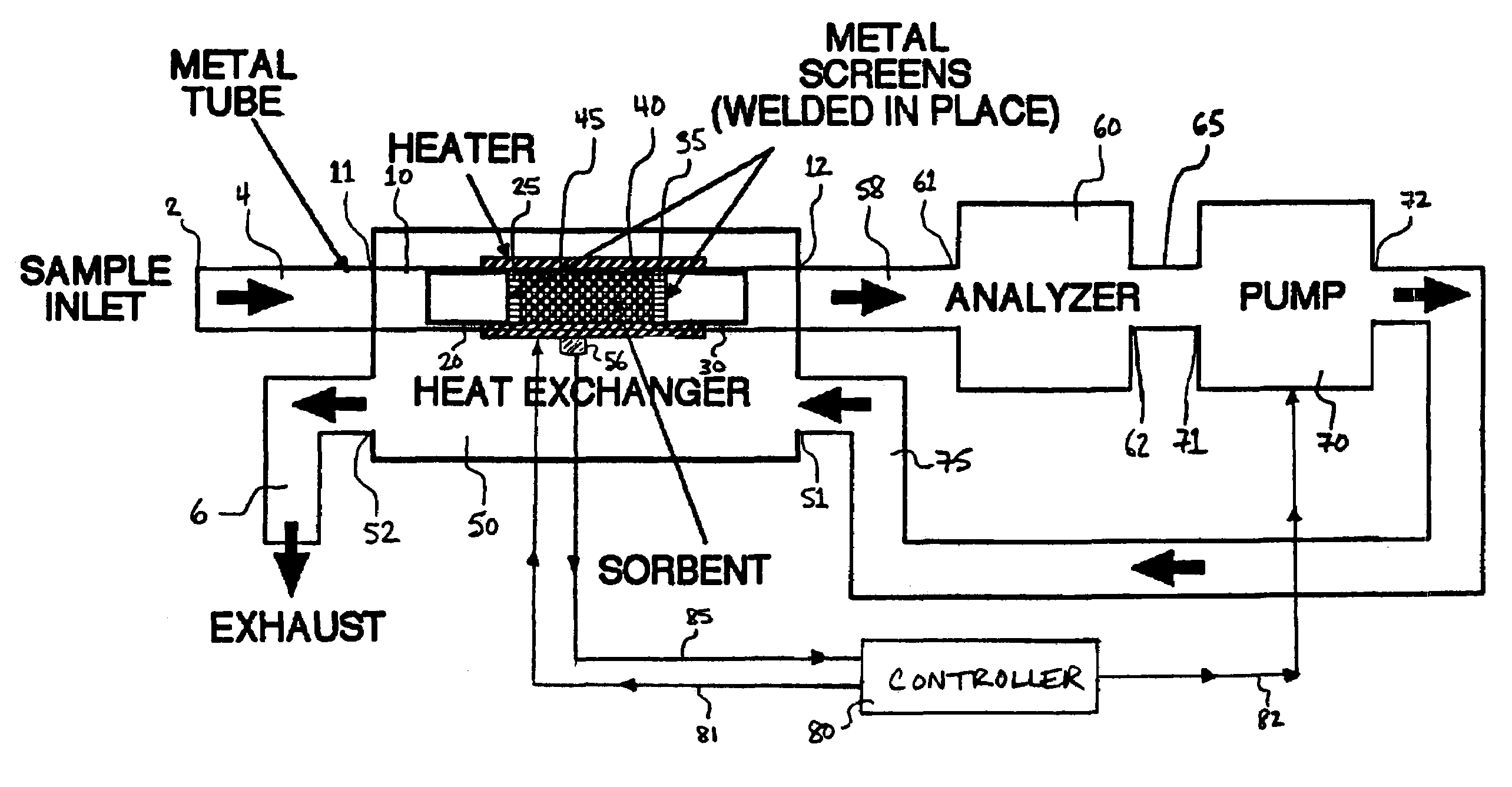
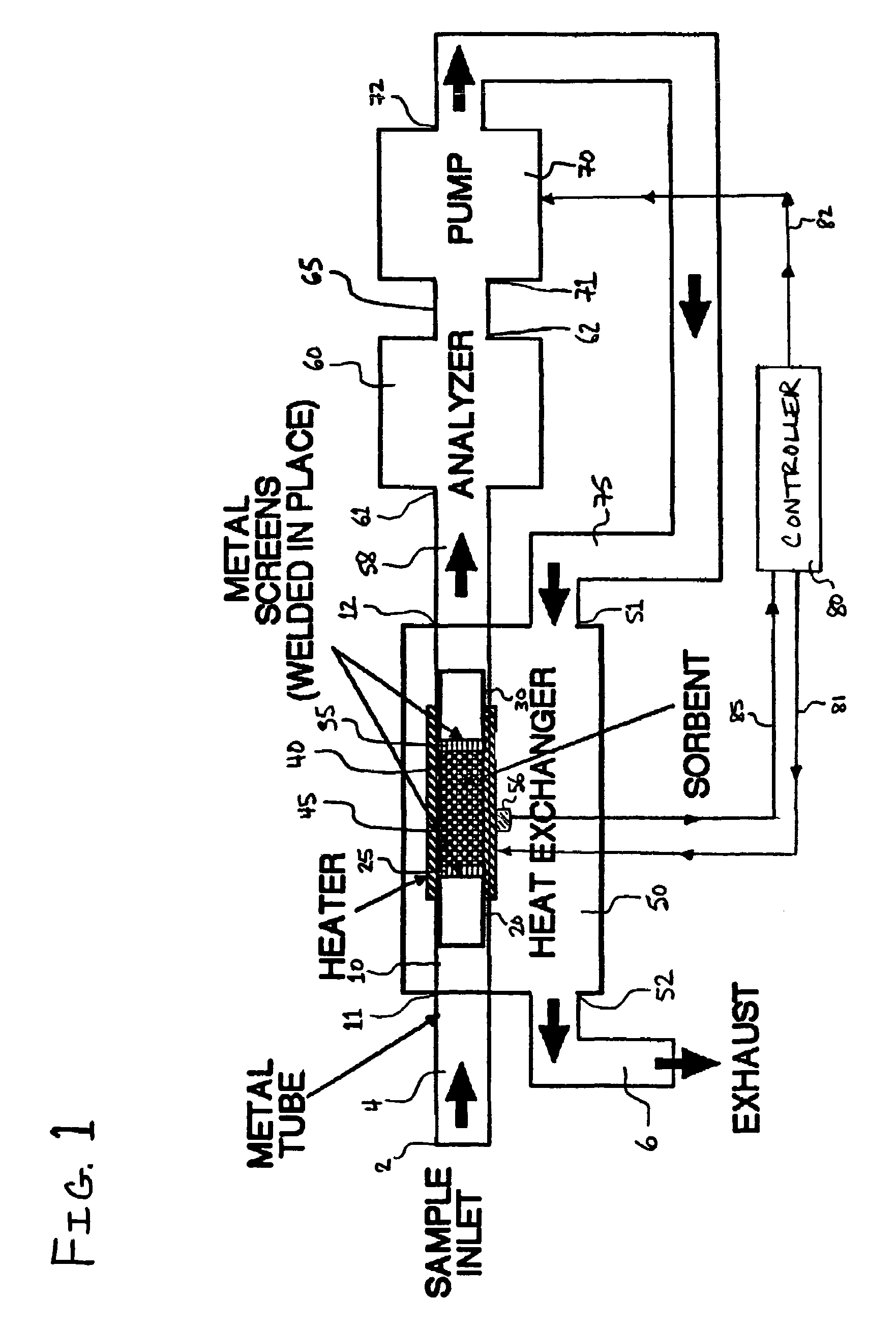
[0020]As indicated above, an important goal of the invention is provision of a concentrated vapor sample suitable for detection and or analysis by a chemical detection instrument in a simple, efficient and repeatable manner. Central features of the invention, which enable attainment of such goal include a metal or metal alloy screen element to retain the sorbent material in a good position for sorbing any vapor of interest present, attachment of each screen element via welding to a desired position on the interior surface of a housing within which the sorbent material is contained, utilization of a housing made from a suitable metal or metal alloy, and cooling of the sorbent material rising exhaust gas from a pump that causes gas flow through the housing interior.

[0021]For purposes of energy efficiency, it is preferred that as many as practical of the components of the device be constructed of metal or metal alloy. It is particularly important for the housing enclosing the sorbent m...


PUM

PropertyMeasurementUnit
lengthaaaaaaaaaa
diameteraaaaaaaaaa
lengthaaaaaaaaaa

Abstract

An apparatus for concentrating a vaporous substance, which comprises: a sorbent material capable of capturing a vaporous substance; a first housing in which the sorbent material is located, a heating element proximate the exterior of the housing; a second housing defining a chamber within which the first housing resides, the first housing being located in said chamber such that there is a space permitting gas flow between the outside of the first housing and the inside of the second housing; and a pump capable of causing an exhaust gas to flow through the space in contact with the outside of the first housing; and methods for making and utilizing such apparatus.

Description

FIELD OF THE INVENTION[0001]The invention relates to technology for concentrating vaporous substances for improved detection by a sensing instrument.BACKGROUND OF THE INVENTION[0002]Detection devices and monitoring and measurement instruments are frequently used for ascertaining the presence and concentration of selected gaseous chemical species in a subject environment. Unfortunately, in many instances, the concentration of the gas or vapor of interest may fall below the effectiveness floor of the technology in question. To address this situation, the art has devised various techniques for the concentration, or enrichment, of the gas or vapor species such that, if the species is present, it can be collected to accumulate its concentration to a level above the detection threshold of the particular technology being utilized.[0003]One attractive conventional enrichment technique involves the use of a vapor sorbent material that serves to sorb (or “trap”) the vapor. If the sorbent mate...

Claims


Application Information

Patent Timeline
Patent Type & Authority Patents(United States)
IPC IPC(8): G01N1/22G01N1/40
CPCG01N1/2214G01N1/40B01D53/0407B01D53/04Y10T436/255B01D53/0438B01D53/0454B01D2253/102B01D2253/106B01D2258/0216B01D2258/0275B01D2259/40096B01D2259/4533G01N1/405G01N1/44G01N2030/085
Inventor WOHLTJEN, HENRYKLUSTY, MARK
Owner MSA TECH
Why Eureka
Try Eureka