
On-site controller for an HVAC system

a technology for heating ventilation and air conditioning, applied in the field of controllers for heating ventilation airconditioning (hvac) systems, can solve the problems of affecting the operation efficiency the determination of the cost of electric power charged by a power company, and the change in the operational capabilities of any hvac system, so as to accurately control the operation of an hvac system, easy installation, and control the effect of cos

Pending Publication Date: 2020-11-12
TAYLOR JAMES ERIC
View PDF22 Cites 0 Cited by
  • Summary
  • Abstract
  • Description
  • Claims
  • Application Information

AI Technical Summary

Benefits of technology

The present invention provides an apparatus for customizing a closed air HVAC system by compiling a database of environmental conditions at the installation site and using it to evaluate changes in the operational conditions of the system. The apparatus includes an environmental sensor and a diagnostic sensor to measure environmental and operational data, which is then used to identify necessary corrective actions. The corrective actions can include adjusting the operating point of fans and compressors in the system. The apparatus also includes a system controller that can handle control of the HVAC system based on information from the database or from the utility. The system controller can also prepare a periodic report based on the deviations of the diagnostic data from the benchmark and changes in kWh measurements. The invention also includes an on-site controller for HVAC systems installed at enclosed facilities, which monitors power demand requirements and ensures compliance with the predefined benchmark.

Problems solved by technology

However, once an HVAC system has been installed for operation at a specified site, its operational efficiency is always significantly impacted by various external factors.
Not surprisingly, it happens that the operational capabilities of any HVAC system will change over time.
Moreover, as implied above, power grid regulations and operating costs always need to be considered whenever an HVAC system is installed.
It is axiomatic that the cost of electric power charged by a power company is determined by the demand for electric power.
It is not surprising that a consequence of using a same generalized power demand profile to establish a uniform cost basis for purchasing electric power at all sites within an extended geographical area is often problematic.
The result here is that the cost for power may not align with the operational requirements of an HVAC system at its location.
Nevertheless, due to microclimate conditions outside an enclosed facility, the power demand of an HVAC system at the facility may be less than what is anticipated by the power demand profile being used by the power company.

Method used


Image

  • On-site controller for an HVAC system
  • On-site controller for an HVAC system
  • On-site controller for an HVAC system

Examples


Embodiment Construction

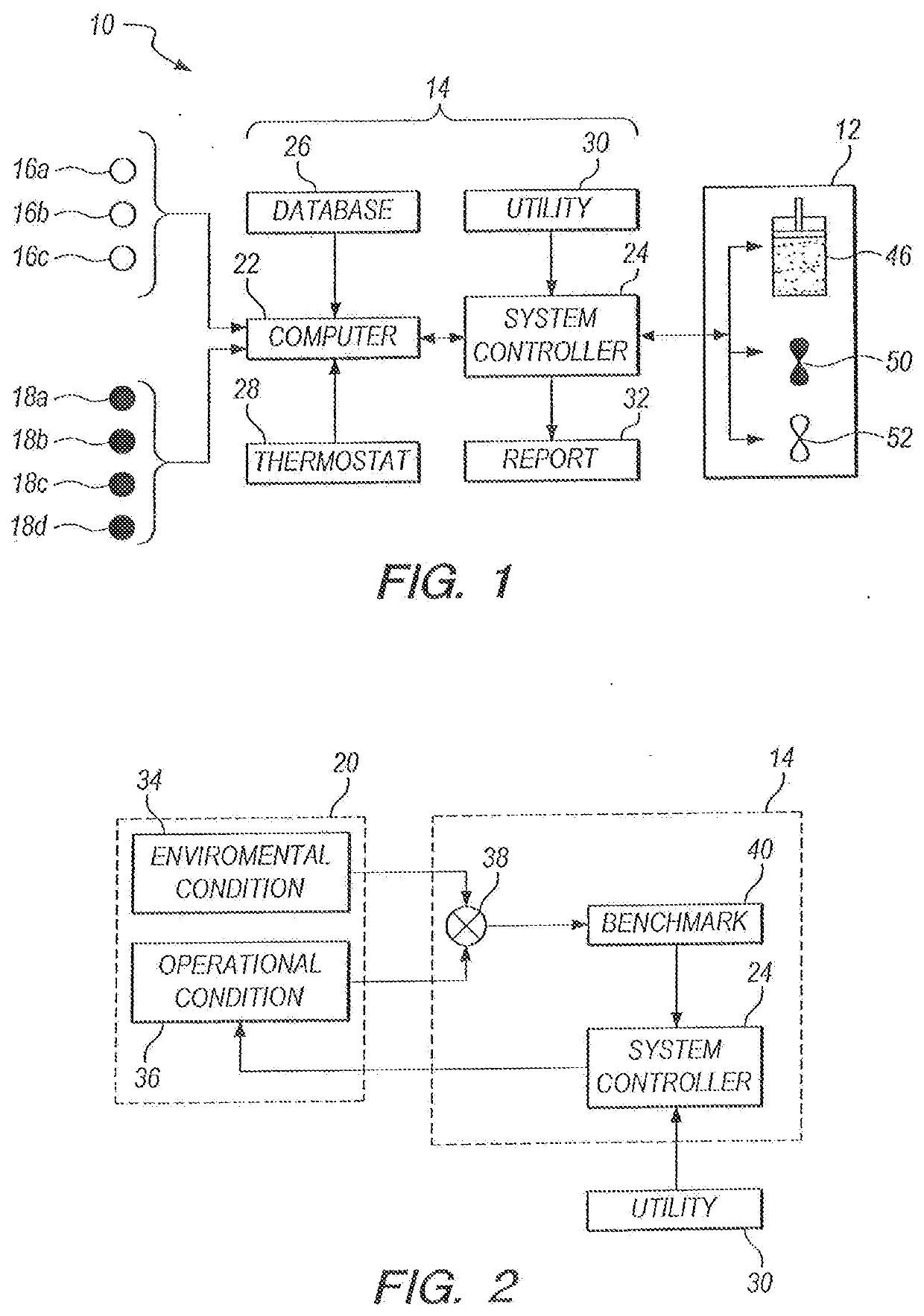
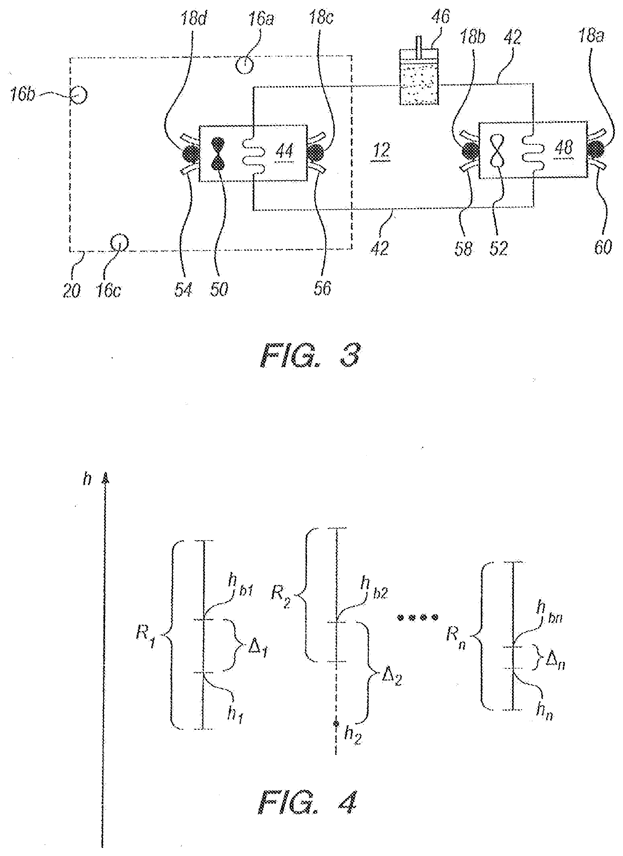
[0035]Referring initially to FIG. 1, an apparatus for customizing air flow in an environment is shown and is generally designated 10. As shown, the apparatus 10 includes a closed air, Heating-Ventilating-Air-Conditioning (HVAC) system 12 of a type well known in the pertinent art. Also, FIG. 1 shows that the apparatus 10 includes a control unit 14 which is connected to the HVAC system 12. Additionally, the apparatus 10 includes a plurality of environmental sensors 16, of which the sensors 16a, 16b and 16c are exemplary; and a plurality of diagnostic sensors 18, of which the sensors 18a, 18b, 18c and 18d are exemplary.

[0036]For purposes of the present invention, the environmental sensors 16a-c are to be positioned at selected locations inside a site 20 (see FIGS. 2 and 3). At the site 20, the environmental sensors 16a-c measure both a temperature and a humidity at each of their respective locations in the site 20. Further, as shown in FIG. 3, the diagnostic sensors 18a-d are employed ...


PUM


Abstract

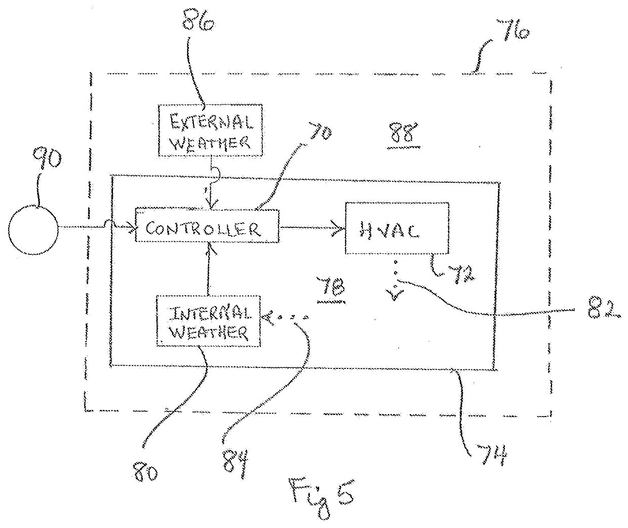
An on-site controller for an HVAC system is operated to maintain temperature and humidity set points inside an enclosed facility. A weather station inside the facility records microclimate data pertinent to environmental conditions inside the facility, and a weather station outside the facility records microclimate data pertinent to meteorological conditions outside the facility. A summing network compares the inside microclimate data with the outside meteorological data to establish an actuating signal. A throttle, responsive to the actuating signal, varies the power demand for the HVAC system to maintain the predetermined set points for environmental conditions inside the facility.

Description

[0001]This application is a continuation-in-part of application Ser. No. 15 / 428,643, filed Feb. 9, 2017, which is currently pending. The contents of application Ser. No. 15 / 428,643 are incorporated herein by reference.FIELD OF THE INVENTION[0002]The present invention pertains to controllers for Heating-Ventilating-Air-Conditioning (HVAC) systems. In particular, the present invention pertains to controllers for operating HVAC systems to maintain optimal temperature and humidity set points within an enclosed facility. More particularly, the present invention pertains to the operation of an HVAC system based on microclimate conditions at the facility. The present invention is particularly, but not exclusively, useful as a controller for controlling the power demand of an HVAC system based on the difference between on-site, microclimate measurements taken respectively inside and outside an enclosed facility.BACKGROUND OF THE INVENTION[0003]HVAC systems are manufactured to have predeterm...

Claims


Application Information

Patent Timeline
Patent Type & Authority Applications(United States)
IPC IPC(8): F24F11/46F24F11/00F24F11/64F24F11/65G05B19/042
CPCF24F11/65F24F2110/10F24F2140/50F24F2110/12F24F2130/10F24F2110/22F24F11/46F24F11/64G05B2219/2614G05B19/042F24F11/0008F24F2140/60F24F2110/20F24F11/63F24F11/88
Inventor TAYLOR, JAMES ERIC
Owner TAYLOR JAMES ERIC
Learn More