
Chemical-containing formed material of type of heating of whole the material, container for holding chemical-containing formed material, device for heating and transpiring chemical and indicator for chemical to be heated and vaporized

Active Publication Date: 2008-11-11
FUMAKILLA
View PDF18 Cites 1 Cited by
  • Summary
  • Abstract
  • Description
  • Claims
  • Application Information

AI Technical Summary

Benefits of technology

[0024]The whole heated, chemical containing or carrier body so configured in accordance with the present invention has been found to permit the chemical to volatilize stably for an extended time period.
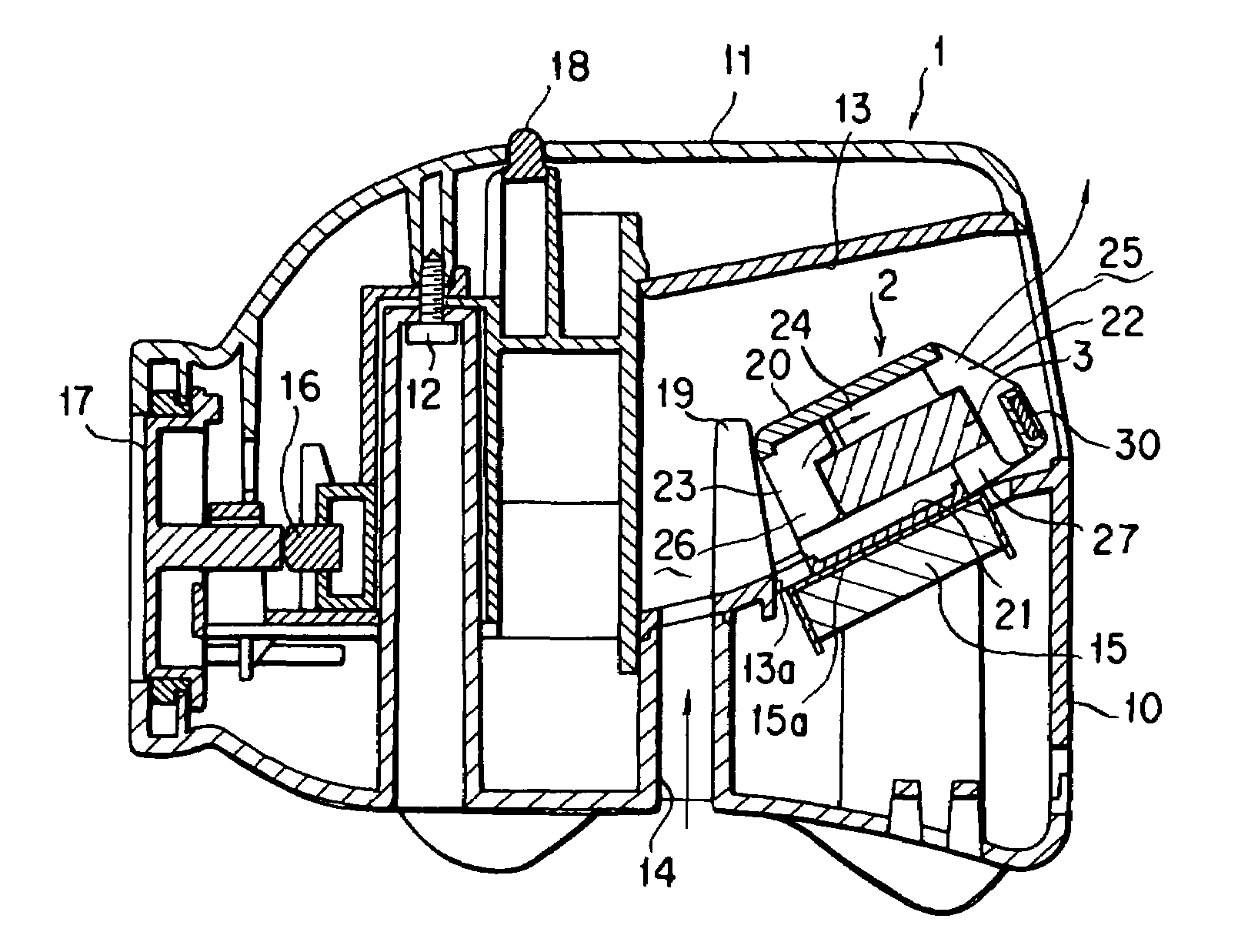
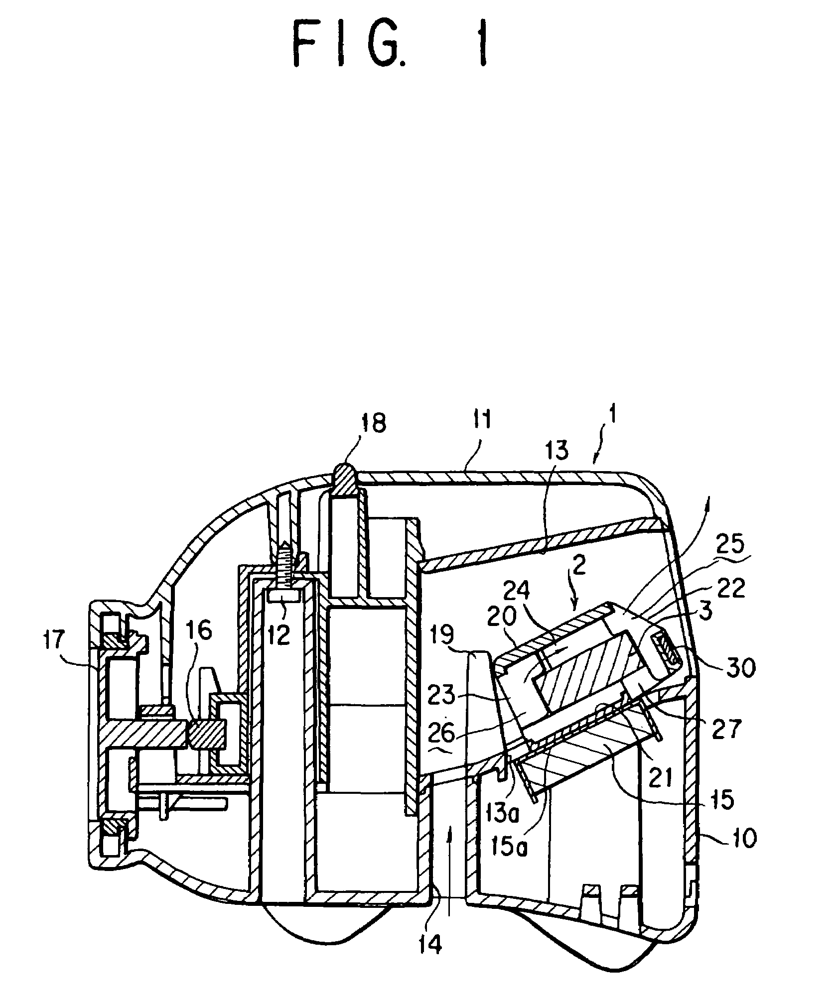
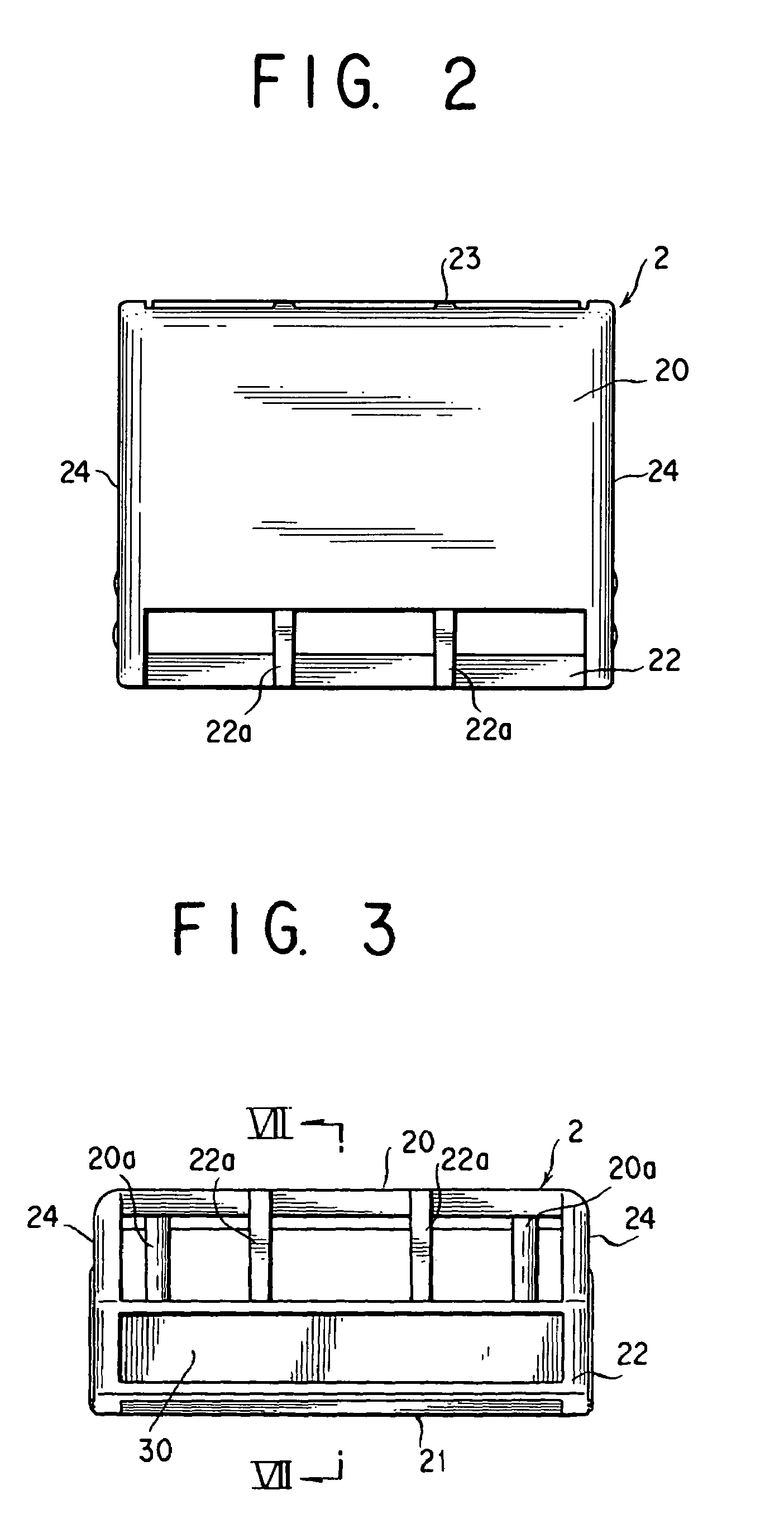
[0028]The chemical containing or carrier body retaining receptacle so constructed in accordance with the present invention has been found to permit vapor of the chemical to pass smoothly between the inner surface of the receptacle and the surface of the chemical containing body and to diffuse through a vent hole into its outside.
[0030]The chemical heating, volatilizing apparatus so constructed in accordance with the present invention provides an arrangement with an inclined heat releasing surface of the heater element whereby the chemical containing body is heated in whole and the apparatus can be made up in a compact design.
[0032]According to this aspect of the present invention, the presence in the indicator of two marks, i.e., a first mark changing from visible to invisible and disappearing and a second mark changing from invisible to visible and appearing enables the user to clearly recognize, and hence permits clearly conveying to the user, the depletion of the effective ingredient of the chemical when its end point is reached.
[0034]According to the preceding specific form of implementation of the present invention, the combined change in visibility and invisibility of the first and second marks enables the user to clearly recognize, and hence permits clearly conveying to the user, the depletion of the effective ingredient of the chemical when its end point is reached.
[0036]According to the preceding specific form of implementation of the present invention, observing the first mark gradually disappearing and the second mark gradually appearing enables the user to clearly-recognize, and hence permits clearly conveying to the user, the state of use of the chemical, i.e., the remaining amount of the effective ingredient of the chemical at any time stage of service thereof.

Problems solved by technology

However, the need for the section where the liquid chemical with the chemical dissolved in the solvent is retained, i.e., a chemical storage container and the section where it is heated to be held separately each from other and the need for the liquid chemical drawn up to be lower in viscosity, hence for the liquid chemical in its storage container to be thinner in chemical's concentration and thus to be larger in volume are entailed, which give the apparatus a disadvantage that it must on the whole be relatively large in size.
Otherwise, not only is the chemical discharged but also the solvent must be emitted into the atmosphere, possibly affecting the environment adversely.
This also makes it unnecessary to hold the chemical in a constant density as required in the partially heated system.
With no additional emission of such as solvent, therefore, the whole heated system is by nature pro-environmental.
The known, whole heated, chemical volatilizing apparatus using the conventional, whole heated, chemical containing body, however, makes it extremely difficult to cause the chemical to volatilize stably for a long time period.
That is, the conventional whole heated, chemical containing body used in the whole heated, chemical volatilizing apparatus so far made has had a thickness of around 2 mm, which has so limited its chemical content that it cannot keep the chemical volatilizing for long.
But, the household use of the chemical heating, volatilizing apparatus imposes a limitation on its plane geometrical size from a requirement for its portability and from a limitation such as of the space of its set place.
Also, requirements based on power consumption by the heater element impose a limitation on its plane geometrical size and in turn that of the chemical containing body.
However, merely presenting a change from a colorless to a colored appearance or from one color to another color makes it obscure and hard to discriminate the end point, and thus makes it difficult for the user to notice the depletion of the effective ingredient of the chemical.

Method used


Image

  • Chemical-containing formed material of type of heating of whole the material, container for holding chemical-containing formed material, device for heating and transpiring chemical and indicator for chemical to be heated and vaporized
  • Chemical-containing formed material of type of heating of whole the material, container for holding chemical-containing formed material, device for heating and transpiring chemical and indicator for chemical to be heated and vaporized
  • Chemical-containing formed material of type of heating of whole the material, container for holding chemical-containing formed material, device for heating and transpiring chemical and indicator for chemical to be heated and vaporized

Examples


first embodiment

[0151]Mention is next made of the indicator 30 according to the present invention.

[0152]Here, the base layer 31 is white, while the color and shade changing layer 32 is white before its color and shade changing and is red after its color has been changed.

[0153]The printed layer 33 as shown in FIG. 10 has characters “START”, a first mark representing the chemical's start point printed in red, characters “END”, a second mark representing the chemical's end point printed in white, and an arrow headed from the “START” characters' side towards the “END” characters' side printed, thereon.

[0154]That arrow is graduation printed so that its “START” characters' side is printed in red, becoming thinner towards its “END” characters' side that is printed in white.

[0155]The indicator 30 when the heating, volatilization of the chemical is started presents the appearance as shown in FIG. 11, at the stage (a) that the “START” characters and only a root portion of the arrow closer to those characters...

second embodiment

[0161]Mention is next made of the indicator 30.

[0162]Here again, the base layer 31 is white, while the color and shade changing layer 32 is white before its color and shade changing and is red after its color has been changed.

[0163]As shown in FIG. 12 the printed layer 33 in addition to having the characters “START” printed in red and the characters “END” printed in white has here, a first band region 35 printed in white, a second band region 36 printed in red lighter in shade, a third band region 37 printed in red somewhat darker in shade, and a fourth band region 38 printed in red identical in shade to the “START” characters, thereon in succession between its opposite ends.

[0164]The indicator 30 when the heating volatilization is initiated presents the appearance as shown in FIG. 13, at the stage (a) that the “START” characters and the second, third and fourth band regions 36, 37 and 38 are visible.

[0165]With a lapse of the chemical's heating time, the color and shade changing lay...

third embodiment

[0170]Mention is next made of the indicator 30 with reference to FIGS. 14 and 15.

[0171]As shown in FIG. 14, the printed layer 33 made of a transparent film has a left hand side half 33a printed in red except for characters “Yes” and its remaining right hand side half 33b printed in white except for characters “No”.

[0172]The printed layer 33 further has characters “Serviceable” printed in white to the left of the characters “Yes” transparently taken out in the left hand side half 33a.

[0173]When the chemical's heating volatilization is initiated, the indicator 30 here presents the appearance as shown in FIG. 15, at the stage (a) that the characters “Serviceable Yes” are visible.

[0174]With the lapse of the chemical's heating time, the color and shade changing layer 32 is gradually changing its color and shade to red, and the indicator 30 is changing its appearance such that the characters “Yes” are becoming gradually darker in shade and invisible from visible while the characters “No”...


PUM


Abstract

Disclosed are a chemical carrier body capable of volatilizing a chemical stably for an extended period of time, a receptacle for retaining the chemical carrier body, an indicator adapted for displaying a degree of consumption of a chemical contained in the chemical carrier body, and a chemical heating, volatilizing apparatus adapted for heating the chemical carrier body.The chemical carrier body retaining receptacle is provided with at least one vent hole and has its inner surface spaced from the carrier body by a distance of 1 to 10 mm.The indicator has a mark gradually disappearing and a mark gradually appearing with a lapse of time of heating.The chemical heating, volatilizing apparatus has a heater element that is lager in size than the bottom surface of the chemical carrier body retaining receptacle and whose heat releasing surface is inclined at an angle of 0 to 70 degrees with respect to the plane on which the apparatus is placed.

Description

[0001]This application is a U.S. National Phase Application under 35 USC 371 of International Application PCT / JP01 / 07728 filed Sep. 6, 2001.TECHNICAL FIELD[0002]The present invention relates to a whole heated, chemical containing body or a chemical carrier body adapted to be heated in whole for volatilization of a chemical contained therein, a chemical containing body retaining receptacle for accommodating such a chemical carrier body therein, and a chemical heating, volatilizing apparatus for heating such a chemical containing body retaining receptacle therein to cause a chemical to volatilize from its carrier body, as well as an indicator for such a heat volatilizing chemical.BACKGROUND ART[0003]A liquid type chemical heating, volatilizing apparatus has been known that is serviceable for a long time period, e.g., 12 hours or more.[0004]Such a liquid type chemical heating, volatilizing apparatus makes use of a liquid chemical formed by dissolving a chemical in a solvent. In the app...

Claims


Application Information

Patent Timeline
IPC IPC(8): A62B7/08A01M1/20A01N25/18A61L9/02A61L9/03
CPCA01M1/2055A01M1/2077A01N25/18A61L9/02A61L9/03
Inventor YAMASAKI, SATOSHIYAMAMOTO, KAZUNORIISHIZUKA, TOMOKO
Owner FUMAKILLA
Learn More