Shared mesh signaling method and apparatus

a signaling method and mesh technology, applied in data switching networks, frequency-division multiplexes, instruments, etc., can solve problems such as inflexibility, bandwidth efficiency, and undesirable set-up period problems of existing mesh protection schemes

Active Publication Date: 2008-11-11
CIENA
View PDF12 Cites 20 Cited by
  • Summary
  • Abstract
  • Description
  • Claims
  • Application Information

AI Technical Summary

Benefits of technology

[0014]The present invention is directed to both local and global implementations of a shared mesh protection scheme for defining an associated protection link when a working connection is established. The shared protection link is used to help protect data traffic in working paths, in the event a network failure of the working paths is detected in a mesh network. Currently, there are flexibility, bandwidth efficiency, and undesirable set-up period problems with existing mesh protection schemes. In the present invention, during implementation of the global protection scheme, the corresponding protection path information is sent down to switch cards of network elements making up the protection path, which consists of a series of protection links including one or more shared protection links. It is recognized that the protection path can be composed of one shared protection link. The protection path information is contained within interrupt driven overhead bytes to provide for failure detection and protection path set-up in a path layer of the mesh network.

Problems solved by technology

Currently, there are flexibility, bandwidth efficiency, and undesirable set-up period problems with existing mesh protection schemes.

Method used


Image

  • Shared mesh signaling method and apparatus
  • Shared mesh signaling method and apparatus
  • Shared mesh signaling method and apparatus

Examples


Embodiment Construction

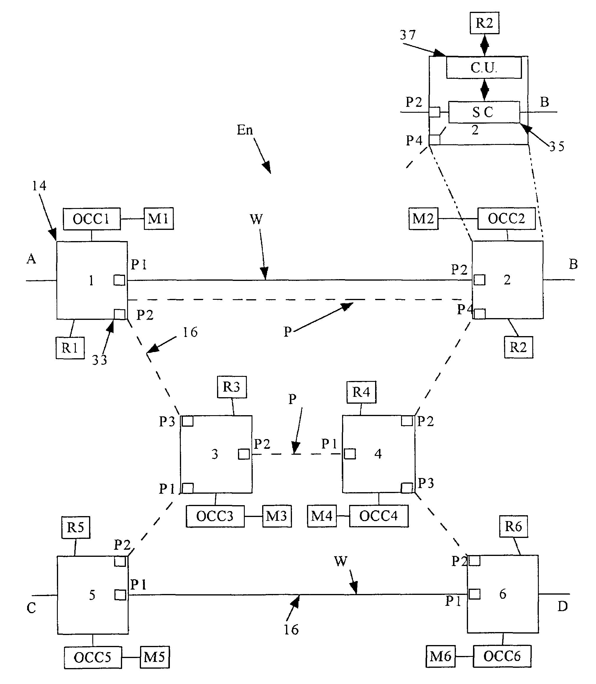
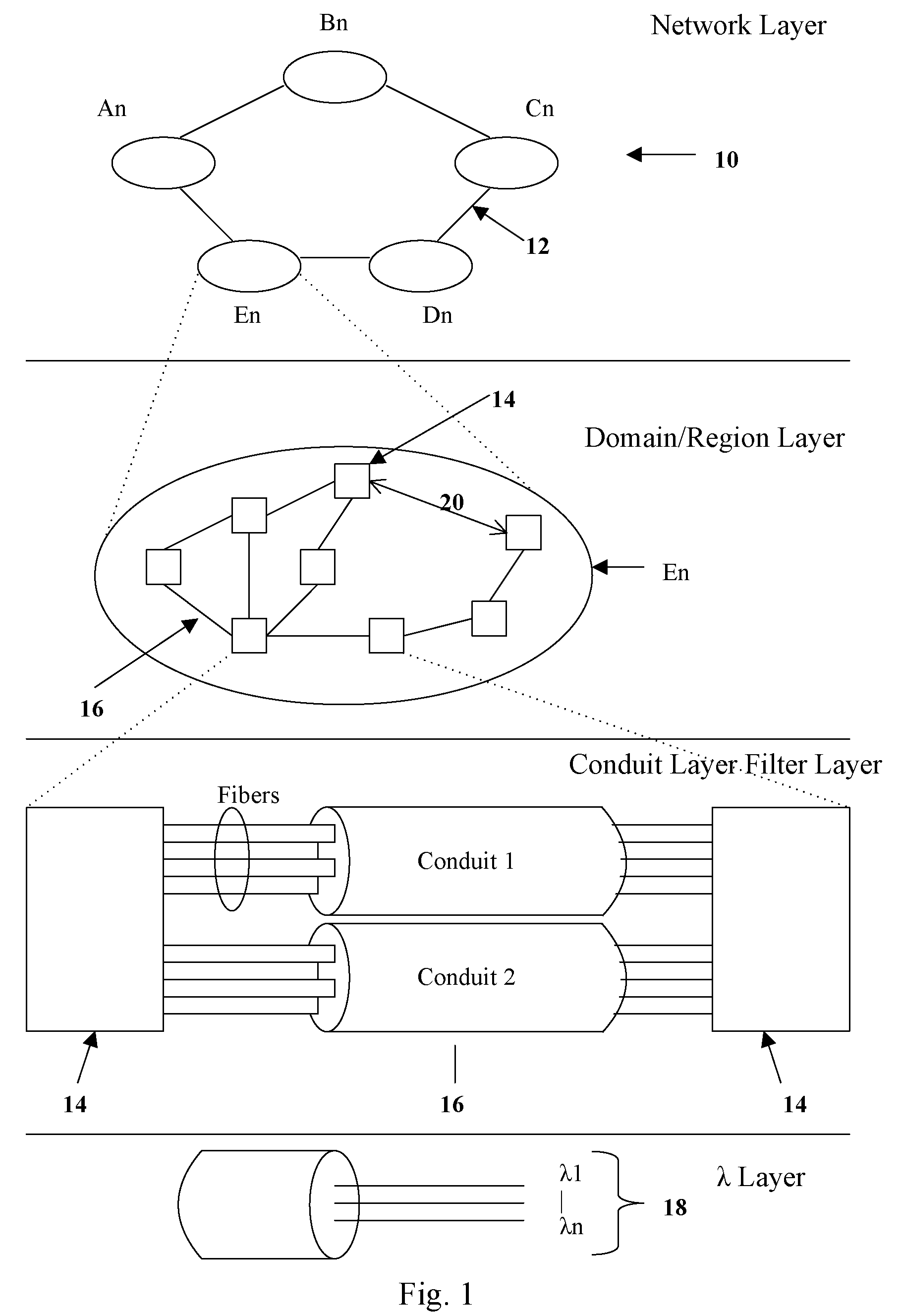
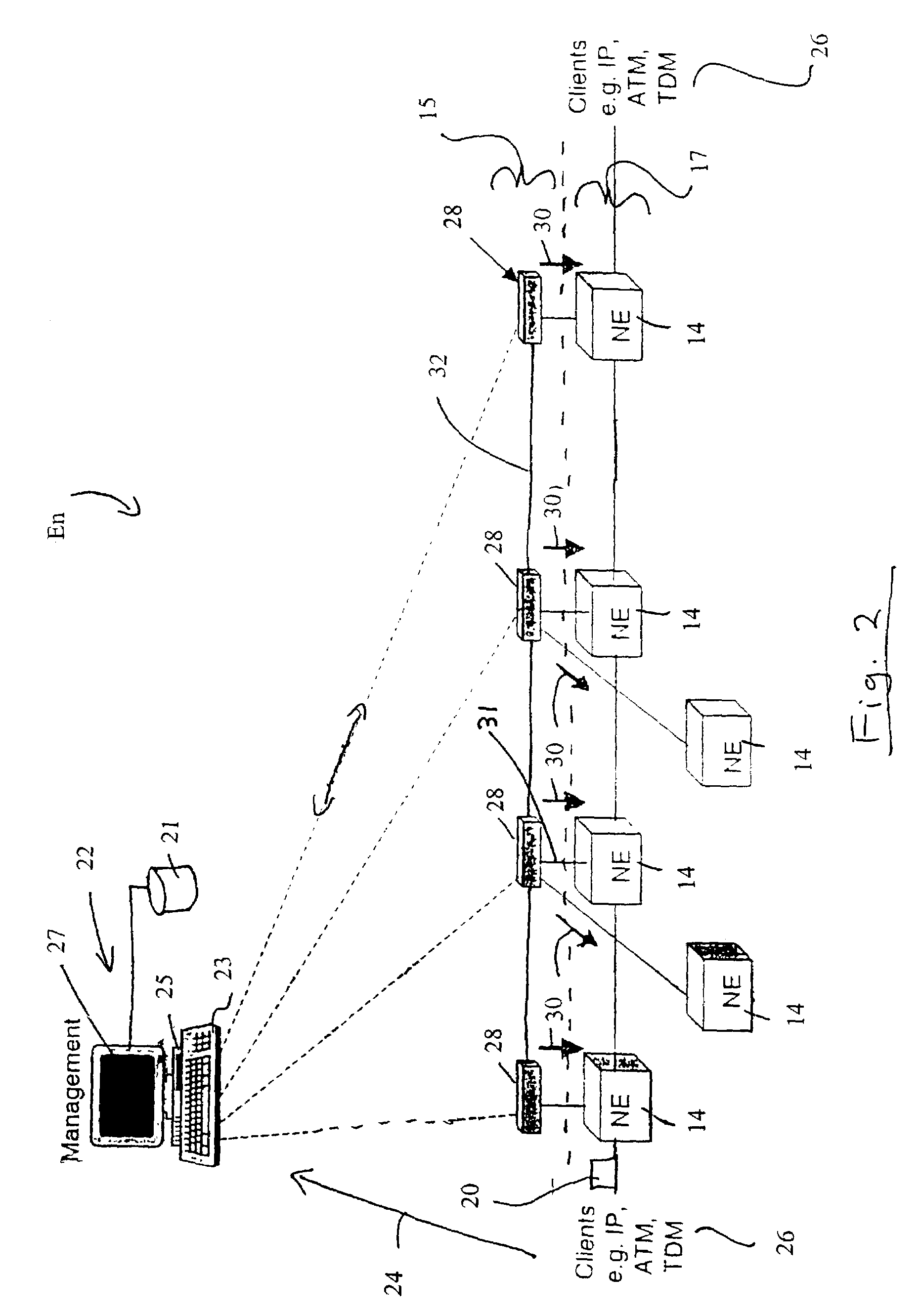
[0033]Referring to FIG. 1, a global telecommunication network 10 contains a series of sub-networks An, Bn, Cn, Dn, En interconnected by bulk data transmission mediums 12. These mediums 12 can consist of such as but not limited to optical fibre, wireless, and copper lines which are collectively referred to as the Backbone Network. Each sub-network An, Bn, Cn, Dn, En contains a plurality of network elements 14 interconnected by conduits 16, which can be collectively referred to as path layer 17 (see FIG. 2). These conduits 16 can consist of fibre optic cables, DSL (Digital Subscriber Loop), cable, and wireless mediums, wherein each conduit 16 can be capable of providing the transmission of multiple wavelengths 18 as required by the telecommunication network 10. The transmission structure of the telecommunication network 10 can be used by a variety of different carriers, such as ILECs, CLECs, ISPs, and other large enterprises to monitor and transmit a diverse mixture of data packets 20...


PUM


Abstract

In a mesh network, a network element for providing protection switching in a 1:N shared mesh protection scheme having a first protection path associated with a pair of working paths selected from the N working paths is disclosed. The network element comprising: (a) a link for connecting the network element to a first working path of the pair of working paths in a path layer of the network, the path layer including a plurality of interconnected network elements; (b) a routing table accessible by the network element, the routing table for having local protection channel information associated with a local protection segment separate from the first protection path, the local protection segment connecting the network element and one of the interconnected network elements adjacent to the network element; and (c) an identification module for using the local protection channel information to identify an available protection channel on the local protection segment in the event of failure of a local working segment of the first working path, the local working segment connecting the network element and said one of the adjacent interconnected network elements; wherein the available local protection channel on the local protection segment is used to switch local network bandwidth from the failed local working segment to the local protection segment after the failure has been detected. Selection functions are also disclosed.

Description

[0001]This is a continuation of U.S. patent application Ser. No. 10 / 059,344, filed Jan. 31, 2002 now U.S. Pat. No. 6,917,759[0002]The present invention relates to optical communication systems and, in particular, to apparatus and methods for providing protection signaling between network elements.BACKGROUND OF THE INVENTION[0003]Optical communication systems have become widely implemented in todays telecommunication networks. The Synchronous Optical Network (SONET) is a standard for Synchronous Telecommunication Signals used for optical transmission based on the synchronous digital hierarchy (SDH). SONET can provide the ability to combine and consolidate traffic through grooming, and can reduce the amount of back to back multiplexing in providing transport services for ATM, SMDS, and Frame Relay, etc. Furthermore, network providers can use SONET network features to reduce the operation costs of the transmission network. The next generation of optical networks may be the optical tran...

Claims


Application Information

Patent Timeline
Patent Type & Authority Patents(United States)
IPC IPC(8): H04L12/26H04L12/28H04L12/56H04J3/08H04Q11/04
CPCH04J3/085H04J2203/0053H04J2203/006
Inventor TRUDEL, RICHARDDE BOER, EVERT E.SHIELDS, JAMES A.
Owner CIENA
Why Eureka
Try Eureka