Method and system for controlling carrier leakage in a direct conversion wireless device

a wireless device and wireless technology, applied in power management, transmission monitoring, instruments, etc., can solve the problems that the communication device using the direct conversion process may be susceptible to unmodulated carrier components, and achieve the effects of reducing carrier leakage, improving transmitter gain control precision, and increasing transmitter power level rang

Active Publication Date: 2008-11-11
TEXAS INSTR INC
View PDF2 Cites 2 Cited by
  • Summary
  • Abstract
  • Description
  • Claims
  • Application Information

AI Technical Summary

Benefits of technology

[0005]Some embodiments of the invention provide numerous technical advantages. Other embodiments may realize some, none, or all of these advantages. For example, in one embodiment, the transmitter power level range is increased without a corresponding increase of the carrier leakage by periodically reading the level of carrier leakage at a transmitter output and applying an appropriate direct current offset signal at an input side of the transmitter in order to reduce the carrier leakage. In another embodiment, the precision of transmitter gain control is improved by controlling the gain before the baseband signal is up converted to a transmission signal.

Problems solved by technology

A communications device using the direct conversion process may be susceptible to unmodulated carrier component that may be mixed in with a transmitted output signal of the transceiver chip.

Method used


Image

  • Method and system for controlling carrier leakage in a direct conversion wireless device
  • Method and system for controlling carrier leakage in a direct conversion wireless device
  • Method and system for controlling carrier leakage in a direct conversion wireless device

Examples


Embodiment Construction

[0011]Embodiments of the invention are best understood by referring to FIGS. 1 through 3 of the drawings, like numerals being used for like and corresponding parts of the various drawings.

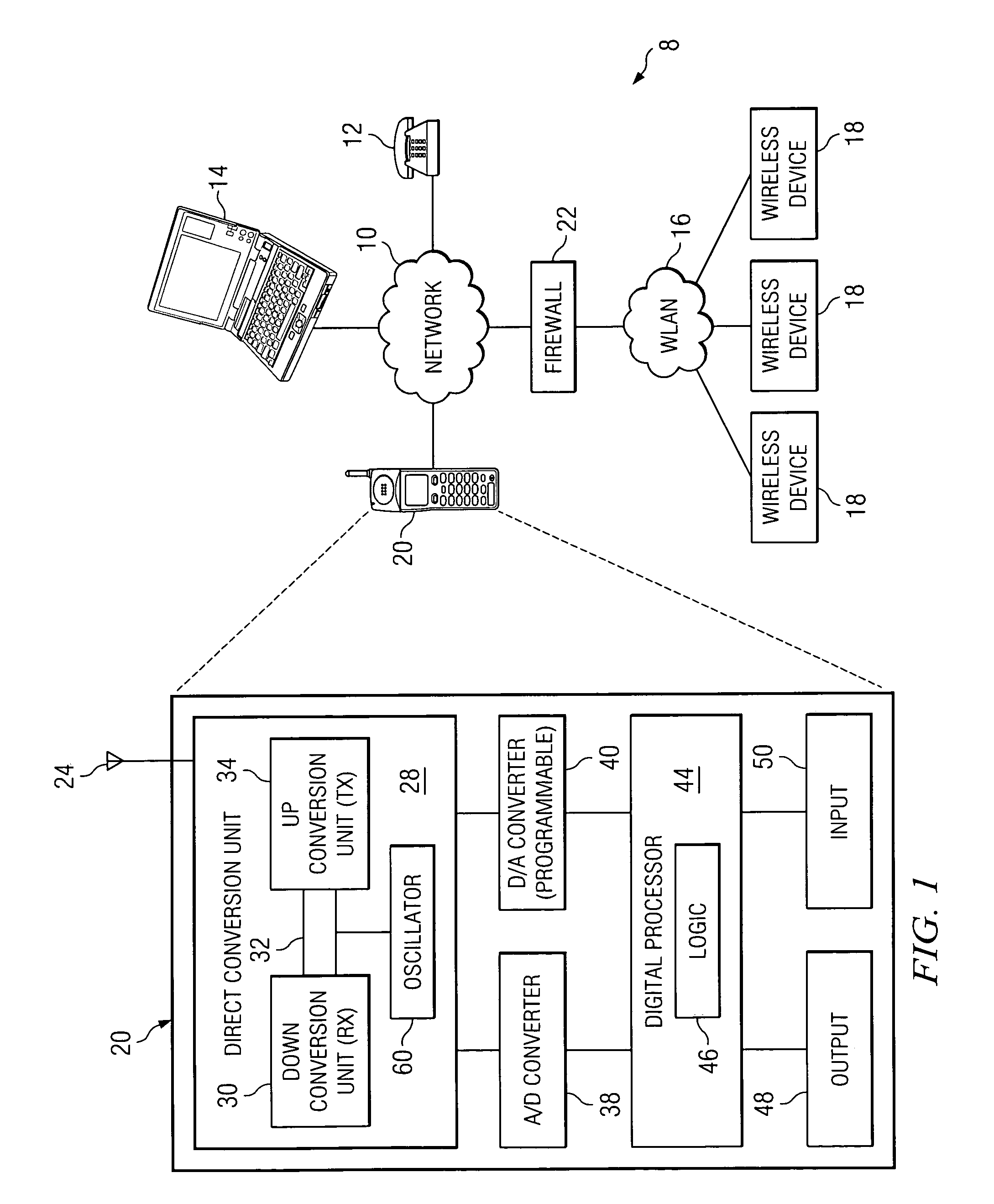
[0012]FIG. 1 is a schematic diagram illustrating one embodiment of a communications system 8 that may benefit from the teachings of the present invention. System 8 includes a communications network 10 that couples communications devices 12, 14, 18, and 20 to each other. Communications devices may be coupled directly to network 10, as shown by communications devices 12, 14, and 20, or coupled through a separate local area network, such as wireless local area network (“WLAN”) 16 as shown in FIG. 1. For example, wireless devices 18 are coupled to network 10 through WLAN 16 and a firewall 22 that protects WLAN 16 from unauthorized access.

[0013]Communications network 10 may include different types of networks. For example, communications network 10 may include a public switched telephone network (“PSTN”...


PUM


Abstract

According to one embodiment of the invention, a system for controlling carrier leakage in a communications device is provided. The system includes a first mixer unit operable to receive a first signal, to convert the first signal into a second signal having a higher frequency than the first signal, and to transmit the second signal. The system also includes a second mixer unit. The second mixer unit is operable to receive the second signal, to convert the second signal into an in-phase signal and a quadrature signal each having lower frequency than the second signal, and to transmit the in-phase signal and the quadrature signal. The system also includes a processor coupled to the first mixer and the second mixer. The processor is operable to perform a leakage reduction procedure by receiving the in-phase signal and the quadrature signal from the second mixer, sampling the in-phase signal and the quadrature signal, determining that a result from the sampling is not equal to a predetermined value, initiating a transmission of a direct current offset signal to the first mixer unit, and adjusting a voltage of the direct current offset signal until a next result of the sampling approximately equals the predetermined value.

Description

TECHNICAL FIELD OF THE INVENTION[0001]This invention relates generally to communications devices and more particularly to a method and system for controlling carrier leakage in a direct conversion wireless device.BACKGROUND OF THE INVENTION[0002]Wireless devices, such as cellular phones and wireless modems, provide a convenient method of communication. Many wireless devices are designed to transmit high frequency signals because of the transmission efficiency and other associated advantages. To transmit a high frequency signal, a wireless device may convert a low frequency signal that represents the input of a user into the high frequency signal for transmission. Also, a wireless device may be required to convert a high frequency signal that it receives from another wireless device and convert the received frequency signal into a low frequency signal so that the converted signal may be processed into an appropriate output form for the user. One method of converting signals is genera...

Claims


Application Information

Patent Timeline
Patent Type & Authority Patents(United States)
IPC IPC(8): H04B1/26H04B7/005H04B17/00H04B17/40
CPCH04B17/354H04W52/52H04W52/346
Inventor DANTONI, FRANCESCOKUMAR, ANIL K V
Owner TEXAS INSTR INC
Why Eureka
Try Eureka