Ink-jet recording apparatus

a recording apparatus and inkjet technology, applied in the direction of typewriters, printing, inking apparatus, etc., can solve the problems of deteriorating ink ejection performance, ejection failure, and thickening of ink contained in a nozzle less often used in printing operations, so as to improve the quality of an image recorded on a recording medium, the effect of deteriorating the ejection performan

Active Publication Date: 2008-11-18
BROTHER KOGYO KK
View PDF6 Cites 5 Cited by
  • Summary
  • Abstract
  • Description
  • Claims
  • Application Information

AI Technical Summary

Benefits of technology

[0006]A higher-speed printing is now demanded of an ink-jet printer. In order to obtain a higher printing speed, it is necessary to shorten a printing cycle, which is a cycle of ejecting an ink droplet. Shortening the printing cycle involves using ink of quick-drying type which enables an ink droplet having landed on a recording paper to dry up instantly. However, when such ink of quick-drying type is used, ink contained in a nozzle may be thickened due to drying, which may deteriorate ink ejection performance or cause ejection failures. A possible way to avoid such a problem is to perform a flushing ejection in a region outside a print region, to eject an ink droplet from a nozzle. With ink of quick-drying type, however, even though the flushing ejection is performed, ink contained in a nozzle which is less often used in a printing operation is thickened. As a result, an ejection of an ink droplet from the nozzle may be delayed, to deteriorate quality of an image recorded on a recording medium.
[0007]An object of the present invention is to provide an ink-jet printing apparatus which is able to restrain ink thickening in a printing operation.
[0008]Another object of the present invention is to provide an ink-jet recording apparatus which is able to restrain a delay in ejection of an ink droplet to thereby form a high-quality image on a recording medium.
[0010]According to the first aspect, the non-ejection frequency detector detects a non-ejection frequency for each nozzle based on the ejection history, and the thickening degree determiner determines a thickening degree of ink in each nozzle based on a continuous non-ejection number and a non-ejection frequency for the nozzle. As a consequence, a thickening degree of ink in each nozzle can be accurately obtained. When a thickening degree of ink in a nozzle becomes equal to or greater than a predetermined value, the waveform signal selector makes the waveform signal output circuit output the second waveform signal so that a non-ejection flushing is performed in the nozzle and ink in the nozzle is stirred to thereby reduce the thickening degree of the ink. As a result, a delay in ejection of an ink droplet from the nozzle hardly occurs, to allow a high-quality image to be formed on a recording medium.
[0012]According to the second aspect, the non-ejection frequency detector detects a non-ejection frequency for each nozzle based on the ejection history, and the thickening degree determiner determines a thickening degree of ink in each nozzle based on a continuous non-ejection number and a non-ejection frequency for the nozzle. As a consequence, a thickening degree of ink in each nozzle can be accurately obtained. When ejecting an ink droplet from a nozzle, the potential controller controls the waveform signal output circuit in such a manner that a drive potential of the ejection waveform signal for making an ink droplet ejected from the nozzle becomes higher as a thickening degree in the nozzle increases. Thus, as a thickening degree of ink in the nozzle is greater, higher ink ejection energy is applied to a corresponding pressure chamber. As a result, a delay in ejection of an ink droplet from the nozzle can be restrained, to allow a high-quality image to be formed on a recording medium.

Problems solved by technology

However, when such ink of quick-drying type is used, ink contained in a nozzle may be thickened due to drying, which may deteriorate ink ejection performance or cause ejection failures.
With ink of quick-drying type, however, even though the flushing ejection is performed, ink contained in a nozzle which is less often used in a printing operation is thickened.
As a result, an ejection of an ink droplet from the nozzle may be delayed, to deteriorate quality of an image recorded on a recording medium.

Method used


Image

  • Ink-jet recording apparatus
  • Ink-jet recording apparatus
  • Ink-jet recording apparatus

Examples


first embodiment

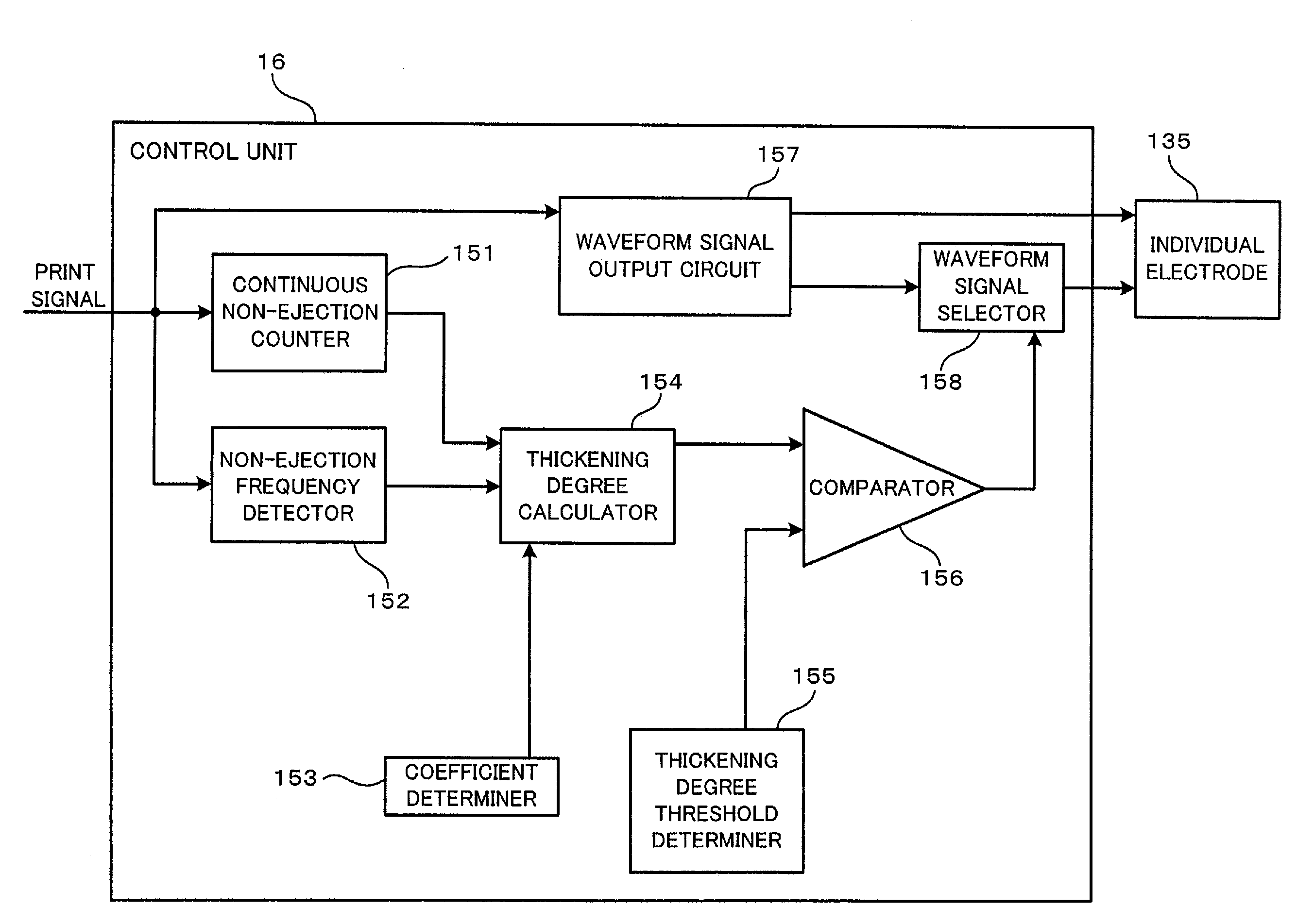
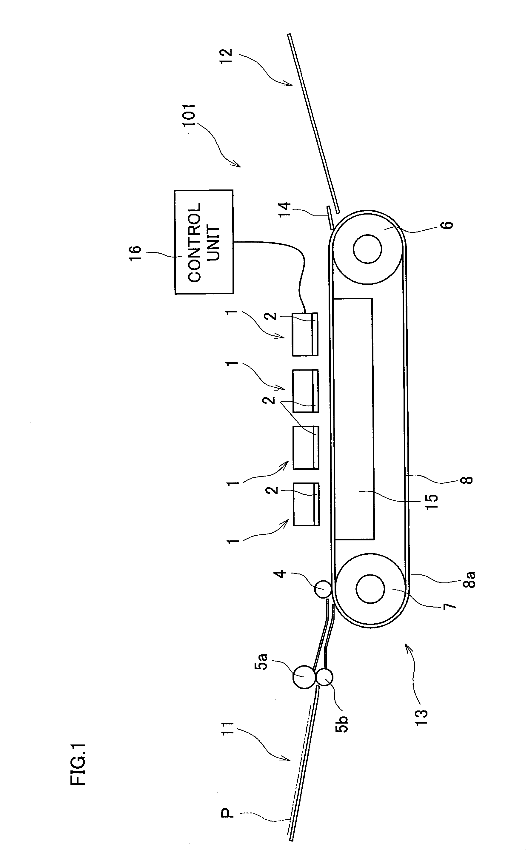
[0033]FIG. 1 illustrates a general construction of a printer, which is an ink-jet recording apparatus, according to the present invention. As shown in FIG. 1, a printer 101 is a line-type ink-jet printer having four ink-jet heads 1 arranged side by side in a horizontal direction in FIG. 1. The ink-jet printer 101 includes a paper feed unit 11, a paper discharge unit 12, and a paper conveyor 13, which are shown in left, right, and middle parts of FIG. 1, respectively. In the printer 101, the control unit 16 controls operations of the ink-jet heads 1.

[0034]Recording papers P, which are recording media for a printing to be performed thereon, are disposed in the paper feed unit 11. In performing a printing, the recording papers P are one by one conveyed rightward in FIG. 1 by a pair of paper feed rollers 5a and 5b. The paper conveyor 13 has two feed rollers 6 and 7, and also has an endless conveyor belt 8 wound on the feed rollers 6 and 7. As the feed rollers 6 and 7 rotate, the conveyo...

second embodiment

[0086]In the first and second embodiment, the first coefficient W1 and the second coefficient W2 are determined based on a temperature of the ink-jet head 1, a kind of ink ejected from the nozzle 108, and a manufacture characteristic value for the ink-jet head 1. However, a first coefficient and a second coefficient may be determined based on only some of them.

[0087]In addition, in the first and second embodiment, the arithmetic operation performed by the thickening degree calculator 154 for calculating a thickening degree includes a calculation of multiplying a non-ejection frequency detection value by the first coefficient W1 and a calculation of multiplying a continuous non-ejection number by the second coefficient W2. However, a thickening degree may be calculated by an arithmetic operation including only one of the calculations. Alternatively, an arithmetic operation performed for calculating a thickening degree may include neither of the calculations, and a thickening degree m...


PUM


Abstract

A waveform signal output circuit selectively outputs, to an ejection energy applier, either one of a first waveform signal so as to make an ink droplet ejected from a nozzle and a second waveform signal so as not to make an ink droplet ejected from the nozzle. A continuous non-ejection counter counts a continuous non-ejection number. A ejection history memory stores therein an ejection history. A non-ejection frequency detector detects a non-ejection frequency. A thickening degree determiner determines a thickening degree of ink in the nozzle. A waveform signal selector makes the waveform signal output circuit output the second waveform signal to the ejection energy applier when an ink droplet is not ejected in the current printing cycle and in addition a thickening degree is equal to or greater than a predetermined value.

Description

CROSS REFERENCE TO RELATED APPLICATION[0001]The present application claims priority from Japanese Patent Applications No. 2006-211754, which was filed on Aug. 3, 2006, and No. 2006-214891, which was filed on Aug. 7, 2006, the disclosures of which are herein incorporated by reference in its entirety.BACKGROUND OF THE INVENTION[0002]1. Field of the Invention[0003]The present invention relates to an ink-jet recording apparatus which performs a printing by ejecting ink droplets.[0004]2. Description of Related Art[0005]An ink-jet head included in an ink-jet recording apparatus which ejects ink droplets to a recording medium such as a recording paper is sometimes provided with a passage unit and an actuator. The passage unit has nozzles which eject ink droplets and pressure chambers which communicate with the nozzles. The actuator applies ejection energy to ink contained in the pressure chambers. The actuator applies pressure to a pressure chamber by changing a volume of the pressure cham...

Claims


Application Information

Patent Timeline
Patent Type & Authority Patents(United States)
IPC IPC(8): B41J29/38
CPCB41J2/04536B41J2/04581B41J2/04588B41J2/04596B41J2/14209B41J3/543B41J11/007B41J2002/14217B41J2002/14225B41J2002/14306B41J2002/14459B41J2202/20
Inventor SUZUKI, KATSUAKI
Owner BROTHER KOGYO KK
Why Eureka
Try Eureka