Compressor with large diameter shrouded three dimensional impeller

a compressor and impeller technology, applied in the direction of liquid fuel engines, vessel construction, marine propulsion, etc., can solve the problems of leaking gas from the gas flow path before it completely traverses, and reducing the efficiency of the compressor

Inactive Publication Date: 2008-11-18
PRAXAIR TECH INC
View PDF11 Cites 3 Cited by
  • Summary
  • Abstract
  • Description
  • Claims
  • Application Information

AI Technical Summary

Problems solved by technology

A problem encountered with the operation of centrifugal compressors is the leakage of gas from the gas flow path before it completely traverses the gas flow path.
This reduces the efficiency of the compressor.
The problem of reduced operating efficiency is of particular concern with large diameter centrifugal compressors.

Method used


Image

  • Compressor with large diameter shrouded three dimensional impeller
  • Compressor with large diameter shrouded three dimensional impeller
  • Compressor with large diameter shrouded three dimensional impeller

Examples


Embodiment Construction

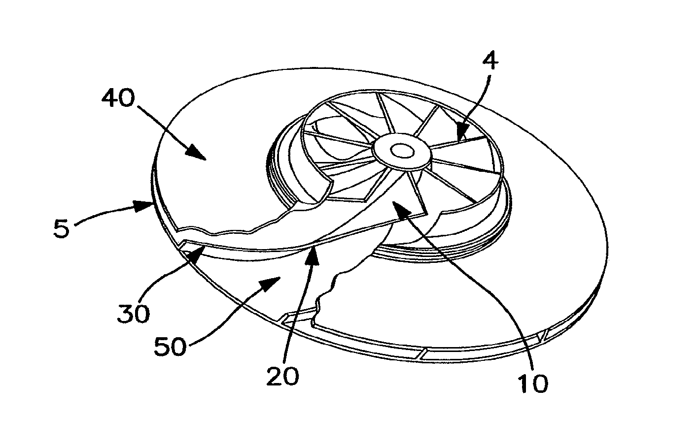
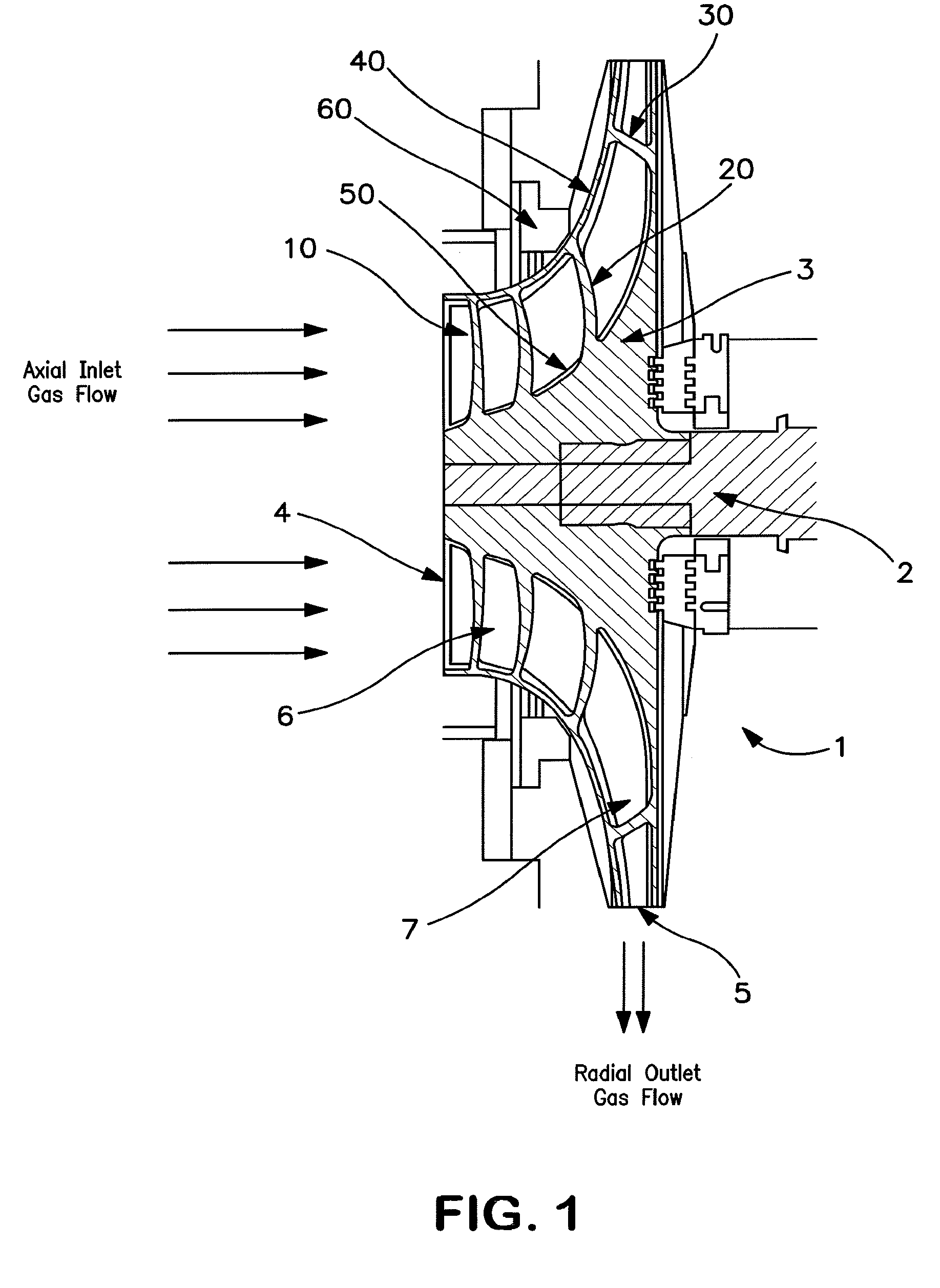
[0009]In general the invention comprises a centrifugal compressor having a large diameter impeller defining a three dimensional gas flow path, i.e. a gas flow path having a significant axial inlet section as well as a radial outlet section with respect to the shaft, with blades in both of these sections having continuous blade geometries between these two sections, and an integral shroud defining the height of the gas flow path. As used herein the term “integral shroud” means a disc-like component shaped to fit the contour of the impeller blade tips at the outermost surface of the impeller gas path, physically attached to the blade tips along their entire edge, so as to be integral with the blades, i.e. without any gaps or discontinuities. Attachment may be by a fabrication technique such as welding, brazing, fastening or adhesion, or may be part of the raw impeller geometry produced by casting, end milling or molding operations.

[0010]The invention will be described in greater detai...


PUM


Abstract

A compressor having a defined large diameter impeller having an integral shroud and having a three dimensional gas flow path defined by the impeller hub surface, blades and the shroud and having a large axially oriented inlet or inducer section with aggressive inducer blades, a defined outlet section geometry, and continuous blade geometries between the inlet and outlet sections.

Description

TECHNICAL FIELD [0001]This invention relates generally to centrifugal compressors and, more particularly, to centrifugal compressors for use in cryogenic rectification systems such as the cryogenic rectification of air to produce atmospheric gases such as oxygen, nitrogen and argon.BACKGROUND ART [0002]A centrifugal compressor employs a wheel or impeller mounted on a rotatable shaft positioned within a stationary housing. The wheel defines a gas flow path from the entrance to the exit. A problem encountered with the operation of centrifugal compressors is the leakage of gas from the gas flow path before it completely traverses the gas flow path. This reduces the efficiency of the compressor.[0003]Large diameter centrifugal compressors are used as feed compressors in the cryogenic air separation, non-cryogenic air separation, and process industries and they also are used as booster compressors at elevated inlet pressures in these and other processes. Large diameter impellers typicall...

Claims


Application Information

Patent Timeline
Patent Type & Authority Patents(United States)
IPC IPC(8): F04D29/26
CPCF04D29/284F04D29/30
Inventor BAKER, ROBERT LEROYABDELWAHAB, AHMEDGERBER, GORDON J.
Owner PRAXAIR TECH INC
Why Eureka
Try Eureka