Cable and apparatus interconnection close quarters environmental seal

a technology of environmental seal and cable and cable, which is applied in the direction of cable junction, cable inlet sealing means, electric cable installations, etc., can solve the problems of easy removal and re-installation, unusable cable to cable interconnection sealing assembly that tapers at either end of a cable diameter, and electrical interconnection subject to degradation

Active Publication Date: 2008-11-18
COMMSCOPE TECH LLC
View PDF29 Cites 17 Cited by
  • Summary
  • Abstract
  • Description
  • Claims
  • Application Information

AI Technical Summary

Benefits of technology

[0028]The seal of the sidewall(s) 19 against the cable 12 and electrical interconnection 17 and against each other may be improved by forming compensation spike(s) 20, best shown in FIGS. 1 and 2, in the sidewalls at a transition area 30 where the sidewall changes from sealing against the cable 12 and apparatus 15 to sealing against the opposing sidewall 19. The compensation spike(s) 20 are formed as additional projections beyond the material calculated to provide a side to side or side to surface contact. The compensation spike(s) 20 provide extra material in the sealing area, increasing sealing pressure in an area that otherwise has been observed to be a primary failure point of this form of seal.
[0030]As best shown in FIGS. 5-7, a generally C-shaped outer shell 13 is dimensioned to seat along the outer diameter 11 of the cylindrical gasket 1, the outer shell 13 having outward protruding edge lip(s) 16 aligned with the insertion opening 3 along the outer diameter 11. The outer shell 13 is semi-flexible, for example formed of a sheet metal or polymeric material. The flexibility of the outer shell 13 allows the edge lip(s) 16 to be spread apart to allow seating of the outer shell 13 over the cylindrical gasket 1. Then, the edge lip(s) 16 may be drawn towards one another to a closed position, closing the insertion opening 3 around the electrical interconnection 17, sealing the sidewall(s) 19 of the insertion opening against and around the cable 12 at the cable end 7, against and around the apparatus 15 at the apparatus end 9 and the remaining sidewall(s) 19 against one another to seal the electrical interconnection 17 within the interconnection cavity 5.
[0036]As shown in FIGS. 11-13, the insertion opening 3 is dimensioned to allow the cylindrical gasket 1 to be placed over the electrical interconnection 17 while requiring minimal distortion of the cylindrical gasket 1, but not so large that the sidewall(s) 19 of the insertion opening 3 can not be easily pulled towards one another as the insertion opening 3 is drawn toward a closed position. For example, the circle sector preferably has an arc length of less than 90 degrees. FIG. 13 also demonstrates how the central aperture 10 portions of the insertion opening 3 at the cable and apparatus ends 7, 9 are dimensioned for ease and evenness of sealing as the edge(s) 16 are drawn together into the closed position, demonstrated by FIG. 14.
[0038]To ease initial insertion friction and improve the seating action of the gasket around the cable 12 and apparatus 15 surfaces, a lubricant may be applied along the sidewall(s) 19 before assembly. The lubricant may be, for example, silicon grease.
[0042]From the foregoing, it will be apparent that the present invention brings to the art a sealing assembly for cable to apparatus connections having improved performance and significant manufacturing and installation cost efficiencies.

Problems solved by technology

Electrical interconnections are subject to degradation from environmental factors such as moisture, vibration and repeated expansion and contraction from daily temperature changes.
Because the connector body is flush against a surface, a cable to cable interconnection sealing assembly that tapers at either end to a cable diameter is unusable.
Further, typical cable to cable interconnection solutions apply a sealing filler to fill the area within the interconnection space creating a permanent rather than easily removable and re-usable seal.

Method used


Image

  • Cable and apparatus interconnection close quarters environmental seal
  • Cable and apparatus interconnection close quarters environmental seal
  • Cable and apparatus interconnection close quarters environmental seal

Examples


Embodiment Construction

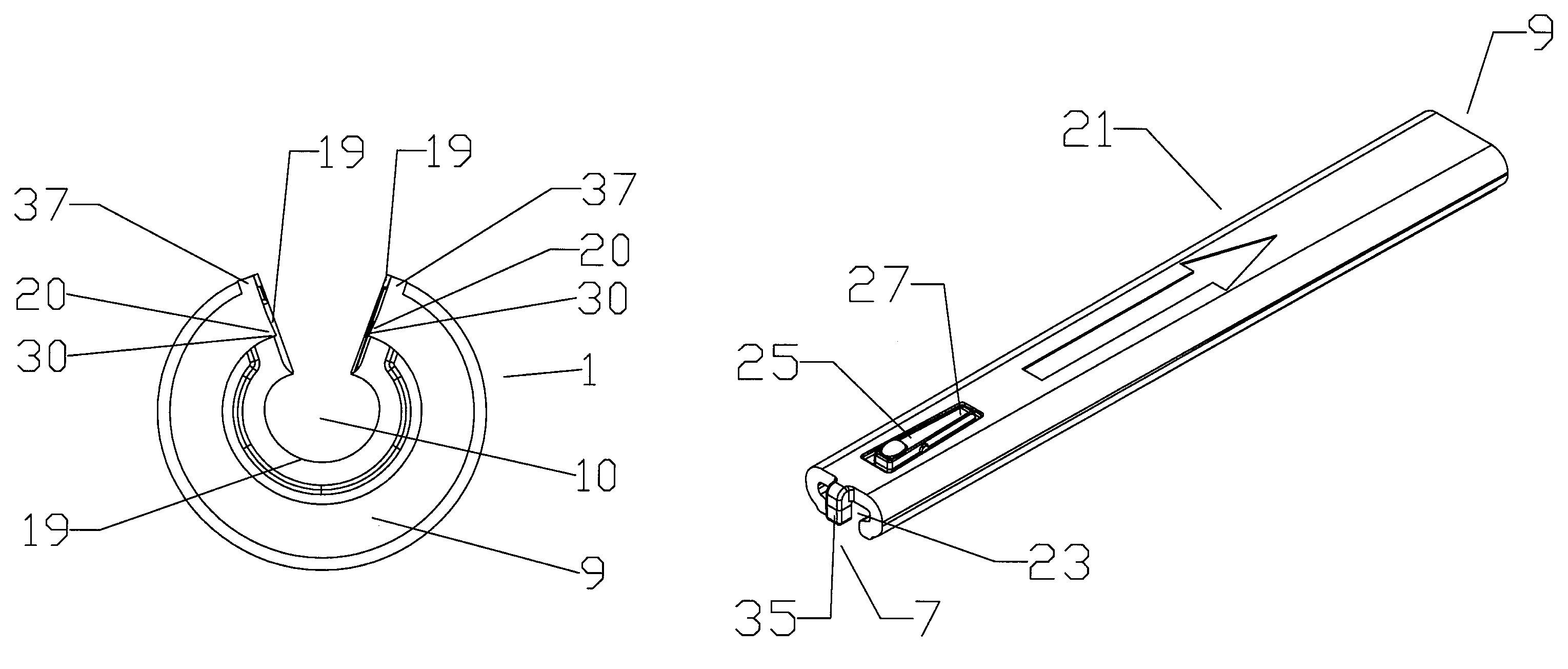
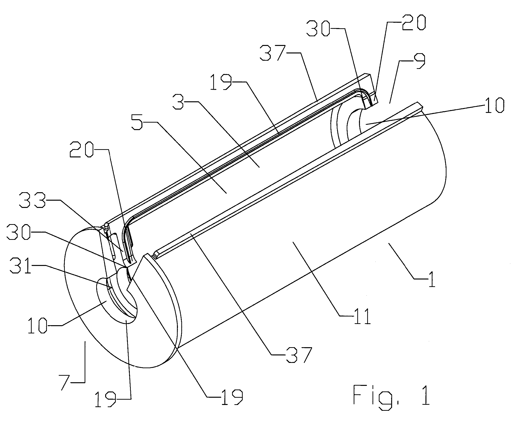
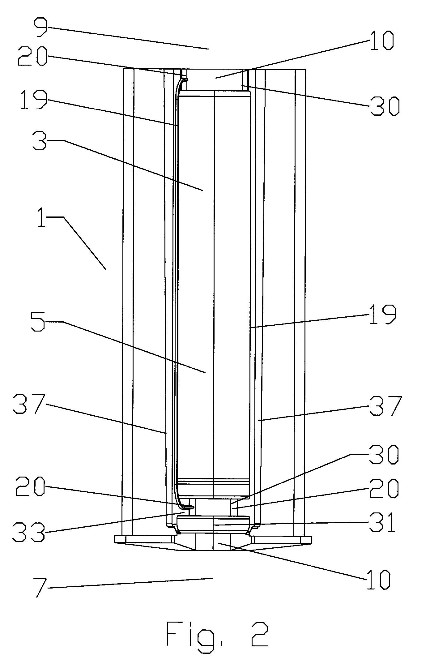
[0025]As best shown by FIGS. 1-4, a sealing assembly according to an exemplary embodiment of the invention has a unitary cylindrical gasket 1 with an insertion opening 3 to an interconnection cavity 5; the insertion opening 3 having a generally circle sector shape at a cable end 7 (FIG. 3) and an apparatus end 9 (FIG. 4), the insertion opening 3 extending between the cable end 7 and the apparatus end 9 along the outer diameter 11 of the cylindrical gasket 1.

[0026]The cylindrical gasket 1 is preferably formed as a unitary portion from a material with deformable and elastic properties, such as rubber or other elastomers.

[0027]The insertion opening circle sector(s) at the cable end 7 and the apparatus end 9 each have a central aperture 10 dimensioned to seat upon the diameter of the expected respective cable 12 and apparatus 15 electrical interconnection 17 around which the sealing assembly will be sealed. The apparatus 15 is demonstrated as a surface mountable connector interface. The...


PUM


Abstract

A sealing assembly for a cable to apparatus electrical interconnection. The assembly having a unitary cylindrical gasket, the outer diameter of the cylindrical gasket provided with an insertion opening to an interconnection cavity; the insertion opening having a generally circle sector shape at a cable end and an apparatus end, the insertion opening extending between the cable end and the apparatus end along the outer diameter. A generally C-shaped outer shell is dimensioned to seat along the outer diameter, the outer shell having outward protruding edge lips aligned with the insertion opening along the outer diameter. The edge lips movable towards one another to a closed position wherein the insertion opening is closed around the electrical interconnection; and means for retaining, such as a locking bar that fits over the edge lips.

Description

BACKGROUND[0001]1. Field of the Invention[0002]The invention relates to sealing an electrical interconnection between a cable and an apparatus, for example a feed and or control cables interconnected with an antenna. More particularly, the invention provides a tool-less weatherproof environmental seal assembly for a cable to apparatus electrical interconnection that is installable in close quarters situations with limited access space around the electrical interconnection.[0003]2. Description of Related Art[0004]Electrical interconnections are subject to degradation from environmental factors such as moisture, vibration and repeated expansion and contraction from daily temperature changes.[0005]Connections to an apparatus, for example an antenna, are typically made to a connector body mounted to an exterior surface of the antenna. Because the connector body is flush against a surface, a cable to cable interconnection sealing assembly that tapers at either end to a cable diameter is ...

Claims


Application Information

Patent Timeline
Patent Type & Authority Patents(United States)
IPC IPC(8): H02G15/08
CPCH02G15/013H02G15/113
Inventor LOW, DAVIDCOX, ALBERTKORCZAK, RICHARD
Owner COMMSCOPE TECH LLC
Why Eureka
Try Eureka