Switching power supply device
a power supply device and power supply technology, applied in the field of switching power supply devices, can solve the problems of increasing the power loss in the power detection circuit, large space and great cost, and requiring large space and great cost, and achieve the effect of improving the power conversion efficiency
- Summary
- Abstract
- Description
- Claims
- Application Information
AI Technical Summary
Benefits of technology
Problems solved by technology
Method used
Image
Examples
first embodiment
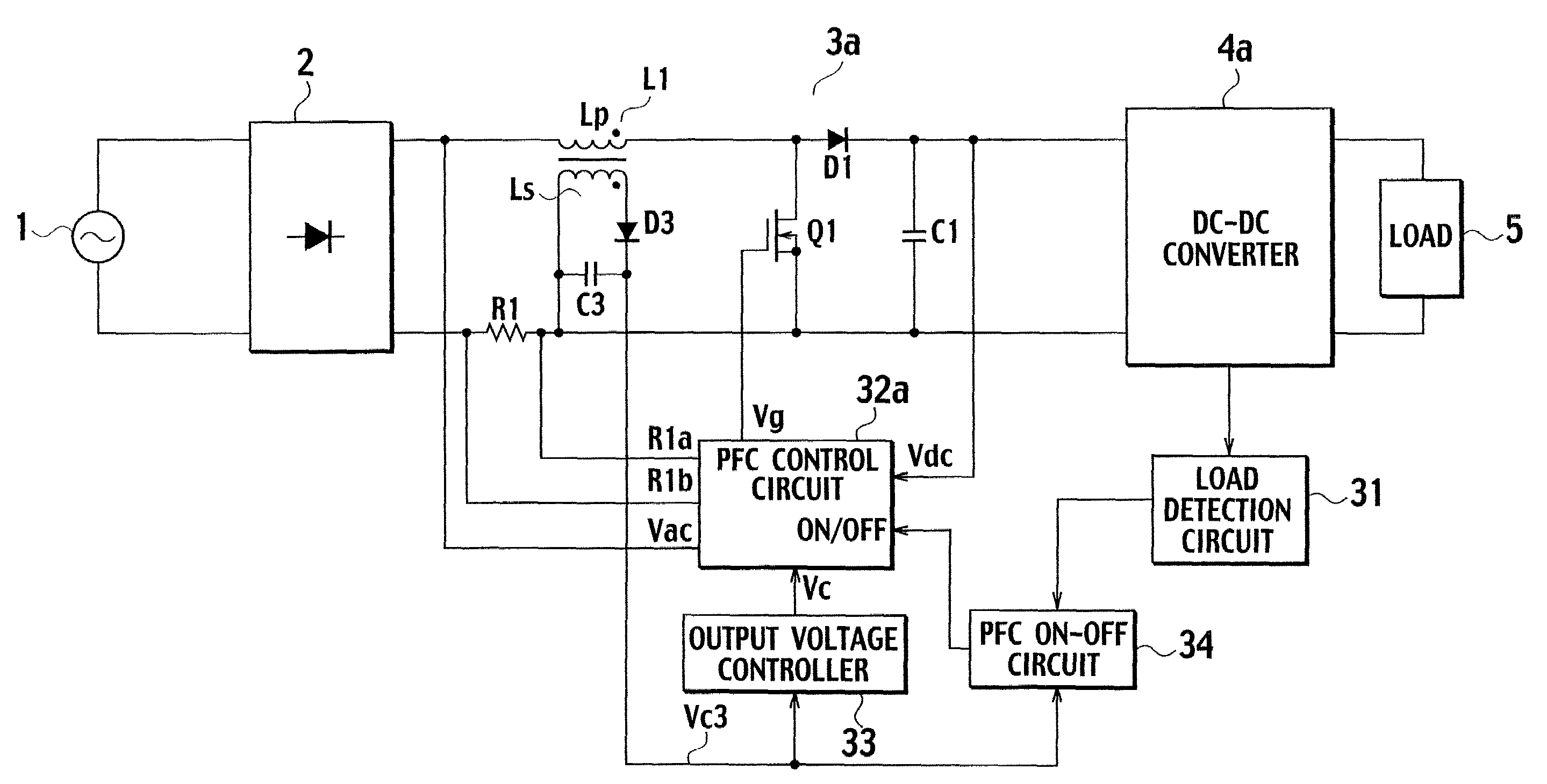
[0043]FIG. 5 is a circuit diagram of a switching power supply device according to a first embodiment of the present invention. In the switching power supply device shown in FIG. 5, the rectifier 2 rectifies an AC input voltage supplied from the AC power supply 1, and outputs the voltage to a PFC circuit 3a. The PFC circuit 3a converts from AC as pulsating wave into DC, and shapes a waveform of the input current rectified in the rectifier 2 so that a waveform of the input current is proportional to that of the input voltage, thereby correcting a power factor and suppressing harmonic components in a current.
[0044]A DC-DC converter 4a converts an output voltage of the PFC circuit 3a into a predetermined voltage to be fed to the load 5. The load detection circuit 31 detects power consumption by the external load 5 of the DC-DC converter 4a. A PFC on-off circuit (power conversion controller) 34 provides an ON signal or an OFF signal to the PFC control circuit 32a so as to enable the PFC ...
second embodiment
[0060]FIG. 9 is a circuit diagram of a switching power supply device according to a second embodiment of the present invention. In the switching power supply device of the second embodiment, an input terminal of the output voltage controller 33 and that of the PFC on-off circuit 34 are connected to output terminals of the rectifier 2 via an AC-DC converting circuit 35, thereby directly detecting the AC input voltage Vac. The AC-DC converting circuit 35 comprises a diode D11 and a capacitor C11. The output voltage controller 33 and the PFC on-off circuit 34 form an input voltage detection circuit. A DC voltage that is outputted via the AC-DC converting circuit 35 and that is proportional to the AC input voltage Vac is referred to as an AC input voltage Vac′ below.
[0061]In the present embodiment, the input voltages to the output voltage controller 33 and to the PFC on-off circuit 34 increase as the AC input voltage Vac increases, and the input voltages to the output voltage controller...
third embodiment
[0069]FIG. 12 is a circuit diagram of a switching power supply device according to a third embodiment of the present invention. In the switching power supply device of the third embodiment shown in FIG. 12, the AC input voltage Vac′ outputted from the rectifier 2 is supplied to the input terminal of the output voltage controller 33, and an output voltage of the PFC circuit (the voltage across the capacitor C1), which varies depending on the AC input voltage Vac, is fed to the input terminal of the PFC on-off circuit 34a.
[0070]Since the output voltage controller 33 and the PFC on-off circuit 34a are identical with those of the second embodiment, operations of the third embodiment are similar with those of second embodiment. Accordingly, similar effects with those of the second embodiment are obtained.
PUM
 Abstract
Description
Claims
Application Information
 - R&D
- Intellectual Property
- Life Sciences
- Materials
- Tech Scout
- Unparalleled Data Quality
- Higher Quality Content
- 60% Fewer Hallucinations
Browse by: Latest US Patents, China's latest patents, Technical Efficacy Thesaurus, Application Domain, Technology Topic, Popular Technical Reports.
© 2025 PatSnap. All rights reserved.Legal|Privacy policy|Modern Slavery Act Transparency Statement|Sitemap|About US| Contact US: help@patsnap.com


