
System and method for the transmission of an audio or speech signal

a technology of audio or speech signal and system, applied in the direction of digital transmission, plural information simultaneous broadcast, broadcast information generation, etc., can solve the problems of low resistance and possible interference-related deterioration, the method is not very resistant to uncooperativeness, and the added synchronization signal is not always audibl

Inactive Publication Date: 2008-11-18
THALES SA
View PDF37 Cites 13 Cited by
  • Summary
  • Abstract
  • Description
  • Claims
  • Application Information

AI Technical Summary

Benefits of technology

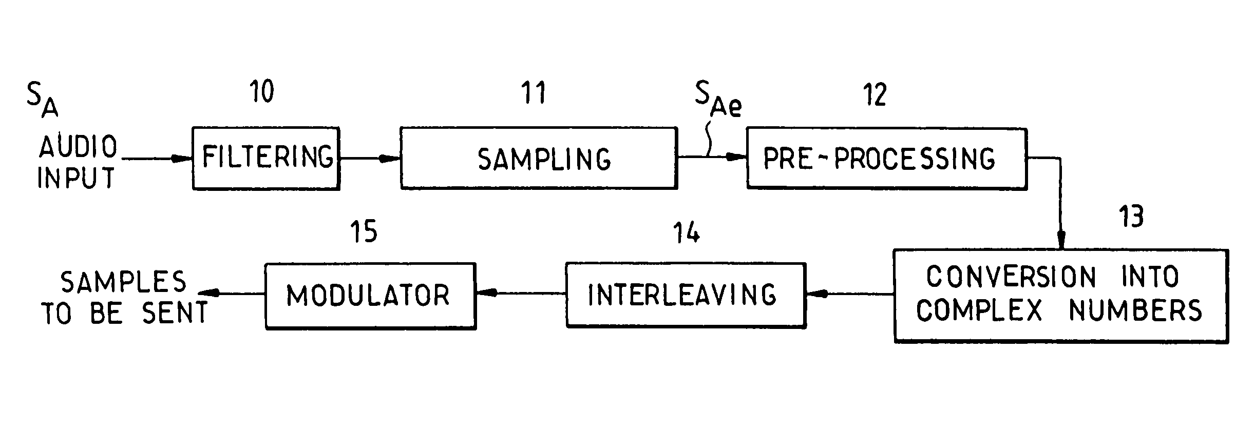
The invention is a new method for transmitting analog signals using a digital type of modem. The method involves replacing the original digital samples with the analog signal to be transmitted. The analog signal is pre-processed before transmission and post-processed at reception. The method can be used for speech or audio signals and offers advantages such as accurate operation, high-quality digital enciphering, economic of resources, and improved signal quality at reception. The method can be used with various types of modulation and is compatible with burst-packet modes. The transmitted signal looks like a classic digital modulation signal.

Problems solved by technology

These are especially low resistance and possible interference-related deterioration.
Another problem is that the added synchronization signal is not always audible.
This method is therefore not very resistant to uncooperative, deciphering attacks, especially because of limits on the number of frequency side bands mixed as a function of the number of points taken in the FFT (Fast Fourier Transformation).
However, this raises certain problems related to bit rate, for example in HF, because there is a limited bit rate available in the conventionally allocated band, 3 kHz, in a digital transmission mode that is resistant to multiple paths (typically, with a spectral efficiency of one 1 bit / Hz / s).
Furthermore, there are limitations when the propagation channel of the signal is highly disturbed.
The systems that implement these principles on the contrary reveal their limits fairly soon.
The quality is quite mediocre and / or the signal loss related to the signal-to-noise ratio finally appears fairly quickly.

Method used


Image

  • System and method for the transmission of an audio or speech signal
  • System and method for the transmission of an audio or speech signal
  • System and method for the transmission of an audio or speech signal

Examples


Embodiment Construction

[0052]In order to have a clearer understanding of the principles implemented in the present invention, the following description shall relate firstly to the transmission of an analog signal through the use of a COFDM type modem.

[0053]The method relies on the following idea: in a transmission system initially comprising digital samples (symbols that can take only a number of given values), the original digital samples at the disposal of the user are replaced by the audio or speech analog signal. The analog signal also takes the place of said original digital samples.

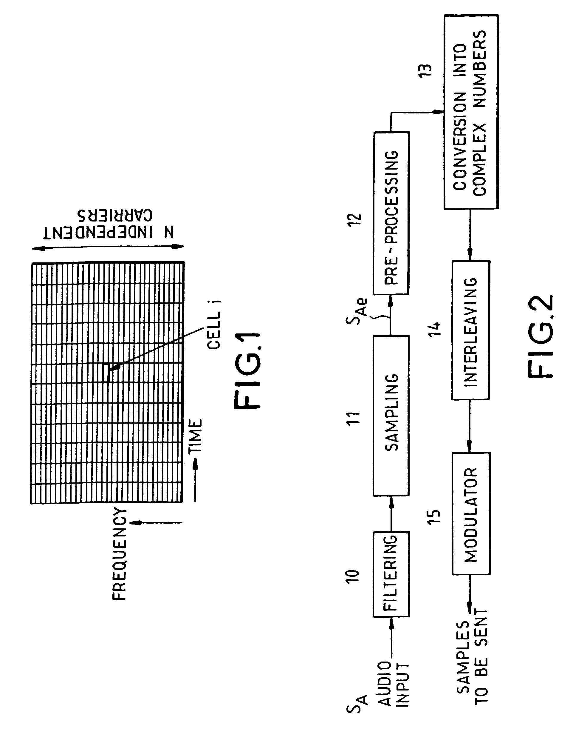
[0054]FIG. 1 shows a diagram of a modem in a time-frequency space.

[0055]This modem may be described as a juxtaposition, in the entire transmission band, of a multitude, for example several hundreds, of elementary narrow-band modems.

[0056]The representation considers a two-dimensional time-frequency space (x-axis and y-axis) divided into independent elementary cells. Each cell indexed i is characterized by a given frequenc...


PUM


Abstract

A system and method for transmitting an analog signal. The analog signal is converted into complex numbers such that two successive audio samples respectively form a real part and an imaginary part of a respective complex number. The complex numbers are then dispersed in a time-frequency space. The complex numbers are then modulated through a digital modulator into temporal signals and the temporal signals are output for transmission. Thereby, a digital modulator conventionally used for modulating digital input signals can operate for the transmission of an analog signal.

Description

BACKGROUND OF THE INVENTION[0001]1. Field of the Invention[0002]The present invention relates to a device and method for the transmission of an analog signal by using a digital type of modem.[0003]Hereinafter in the description, the expression <<digital modem>> designates a modem that receives digital signals at input and gives digital type signals at output. For example, the invention relates to OFDM (Orthogonal Frequency Division Multiplexing), or COFDM (Coherent Orthogonal Frequency Division Multiplexing) type modems or again to serial type modems.[0004]The invention can be applied to audio or speech type analog signals, possibly enciphered signals.[0005]It can be applied also to OFDM type modulation for the high frequencies HF or single-carrier type modulation for the very high frequencies VUHF or again to spread-spectrum modulation, for example by direct sequence or EVF (Evasion Frequency). Single-carrier modulation can also be used in HF and OFDM modulation in VHF....

Claims


Application Information

Patent Timeline
Patent Type & Authority Patents(United States)
IPC IPC(8): H04L27/00H04H20/30H04H60/07H04L27/26
CPCH04H20/30H04H60/07H04L27/00H04L27/2601
Inventor LAURENT, PIERRE ANDRÉDEMEURE, CÉDRIC
Owner THALES SA
Learn More