

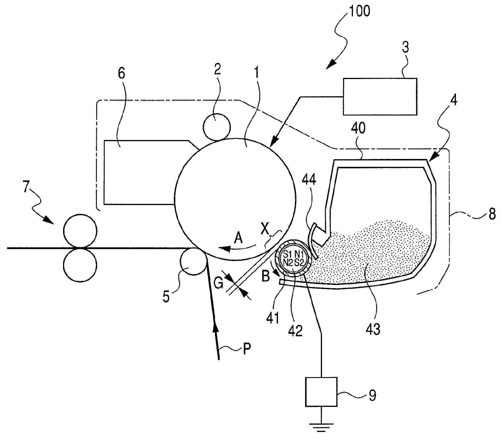
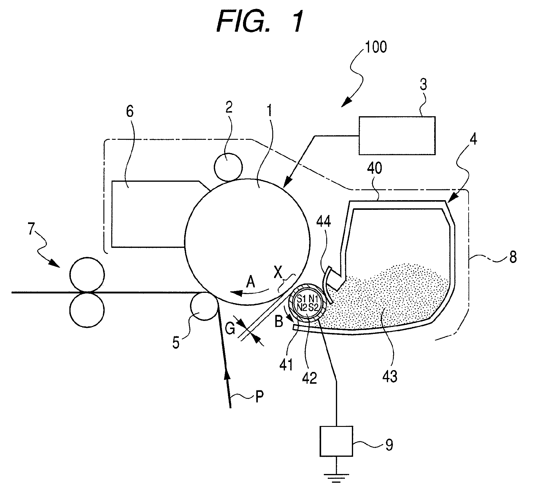
Developing apparatus including a cylindrical developer carrying member conveying a magnetic mono-component developer
a development apparatus and developer technology, applied in the direction of electrographic processes, electrographic processes using charge patterns, instruments, etc., can solve the problems of inapplicability to practical use, increase the risk of fogged images or toner spatter in the apparatus, and the density drop
- Summary
- Abstract
- Description
- Claims
- Application Information
AI Technical Summary
Benefits of technology
Problems solved by technology
Method used
Image

Examples
embodiment 1
[0187]The cartridge (1) in Table 3 was used for a developing apparatus for evaluation purpose. The cartridge (1) was filled with the magnetic toner (1) of Table 2, and inserted into the laser beam printer-LBP-1210 (manufactured by Canon Inc.). A printing test was conducted for an image output of 1000 sheets under room temperature and room humidity (23° C., 60% RH). As an image for durability, a character (8 point) with the coverage rate of 4% image was used. An A4-sized sheet of 75 g / m2 was used as a recording medium.
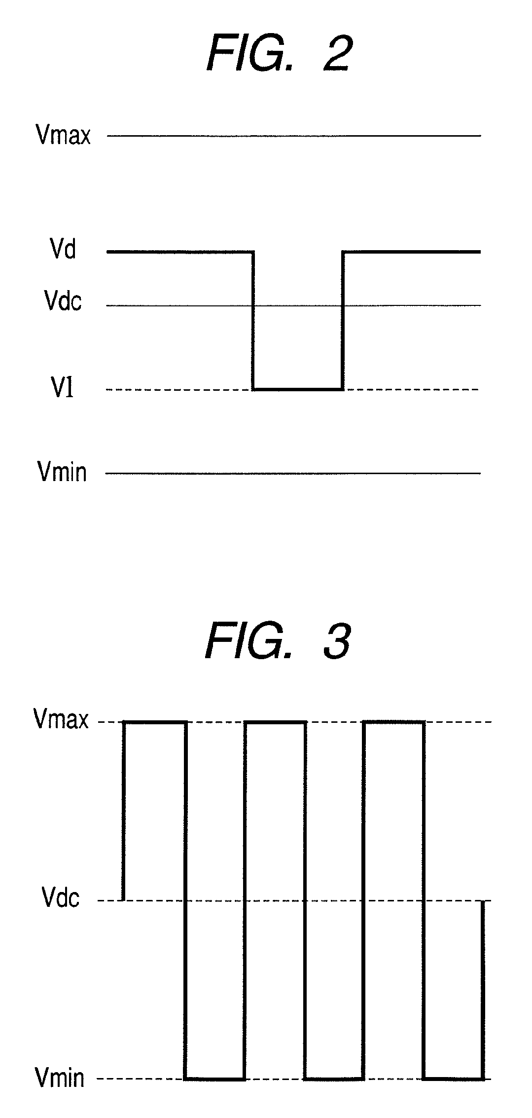
[0188]The latent image potential on the photosensitive drum 1 was set as Vd=−600(V) and Vl=−150(V). The developing bias potential was set as Vpp=1600(V). As a tentative DC bias component, it was set as Vdc=−450(V) and (Vmax=−1250(V) and Vmin=+350(V)). Prior to conducting the printing test for the image-output of 1000 sheet, the Vdc value was adjusted so that the measurement value of the black image of a 5-mm-square printed in the center and the four corners of the print...
embodiments 2 and 3
[0201]As the developing apparatus for the evaluation, the cartridge (1) shown in Table 3 was used and filled with the magnetic toners (2) and (5) shown in Table 2 and a printing test was conducted as in Embodiment 1. Table 4 shows the results.
embodiments 4 , 5
Embodiments 4, 5, and 6
[0202]As the developing apparatus for the evaluation, the cartridge (2) shown in Table 3 was used and was filled with the magnetic toners (1) (2) and (5) shown in Table 2 and a printing test was conducted as in Embodiment 1. Table 4 shows the results. Since the cartridge (2) has the smallest sleeve diameter and the inside magnetic field is weak, some fogged images were observed in the magnetic toner (1) that have a relatively low magnetization. However, the fogged image observed was within an allowable range. When the diameter of the developing sleeve was smaller than 8 mm, which is the value of the present embodiment, the image density was lowered and fogged image was out of the allowable range. Accordingly, the diameter of the developing sleeve should be not less than 8 mm.
PUM
| Property | Measurement | Unit |
|---|---|---|
| outer diameter | aaaaa | aaaaa |
| outer diameter | aaaaa | aaaaa |
| saturation magnetization | aaaaa | aaaaa |
Abstract
Description
Claims
Application Information