Safety method and optoelectronic sensor

a safety method and sensor technology, applied in the direction of forming safety devices, electrical equipment, roll mill control devices, etc., can solve problems such as unwanted switch-off process, and achieve the effect of fast working movemen

Inactive Publication Date: 2008-11-25
SICK AG
View PDF19 Cites 9 Cited by
  • Summary
  • Abstract
  • Description
  • Claims
  • Application Information

AI Technical Summary

Benefits of technology

[0010]It is an object of the invention to provide a safety method and a correspondingly configured sensor which permit fast working movements for a machine tool, with the open gap between the tool parts being made sufficiently safe and vibrations in the direction of the working movement, in particular in the vertical direction, not easily resulting in incorrect switch-offs.
[0016]This minimal monitoring in a last phase prior to the final deactivation of the sensor has the effect that the working movement of the first tool part can also take place with the initial fast closing movement of the machine tool at this point in time. A switching to a slower closing speed is therefore not absolutely required. A continuously fast closing movement is thus possible and the machine tool can be operated at a high work cycle, without the safety of the operator being limited thereby.
[0017]In contrast, the arrangement is, as explained, insensitive with respect to vibrations, in particular with respect to vertical vibrations in the event of a stamping press, up to the final deactivation of the sensor. In summary, the invention thus provides a dynamization of the protected field in dependence on the open gap of the machine tool, with the protected field being adjusted in the center of the remaining open gap—in particular in a symmetrical arrangement—to achieve high insensitivity with respect to vibrations.
[0018]In accordance with a further development of the invention, a normal mode or a box mode can optionally be set for the operation of the machine tool, with the protected field extending along a front space and a back space with respect to the plane of movement of the first tool part in the normal mode. In the box mode, in contrast, an interruption of the light ray only triggers a switch-off process if this interruption takes place both inside the front space and inside the back space. The machining of box-shaped peak pieces, which necessarily partly project into the protected field, is thereby also possible with sufficient safety and high efficiency.
[0019]In accordance with an alternative or additional further development of the invention, a normal mode or a stop mode can optionally be set for the operation of the machine tool, with the protected field extending along a front space and a back space with respect to the plane of movement of the first tool part in the normal mode. In the stop mode, in contrast, the protected field is deliberately muted within part of the front space and / or of the back space so that a tool stop can enter into the muted part without an interruption of the light ray caused thereby triggering a switch-off process. Stop elements can thereby be used, for example for the bending of short limbs, which project into the protected field during the explained movement of said protected field without unwanted and unnecessary downtimes resulting.

Problems solved by technology

The protected field can namely be arranged at such spacing from both tool parts due to its smaller extent that, in the event of the explained vibrations, neither of the tool parts interrupts the light ray and thus triggers an unwanted switch-off process.

Method used


Image

  • Safety method and optoelectronic sensor
  • Safety method and optoelectronic sensor
  • Safety method and optoelectronic sensor

Examples


Embodiment Construction

[0027]The following description of the preferred embodiments is merely exemplary in nature and is in no way intended to limit the invention, its application, or uses.

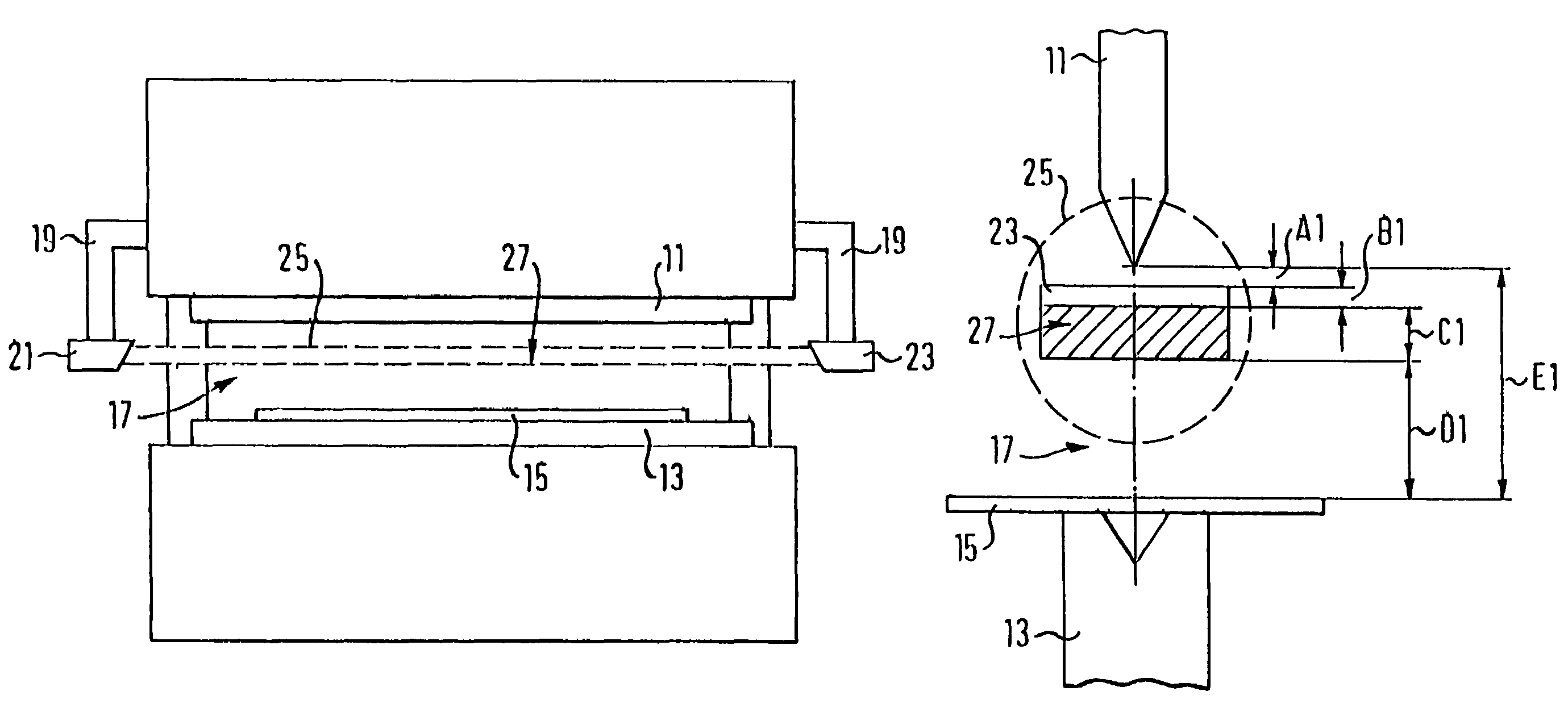
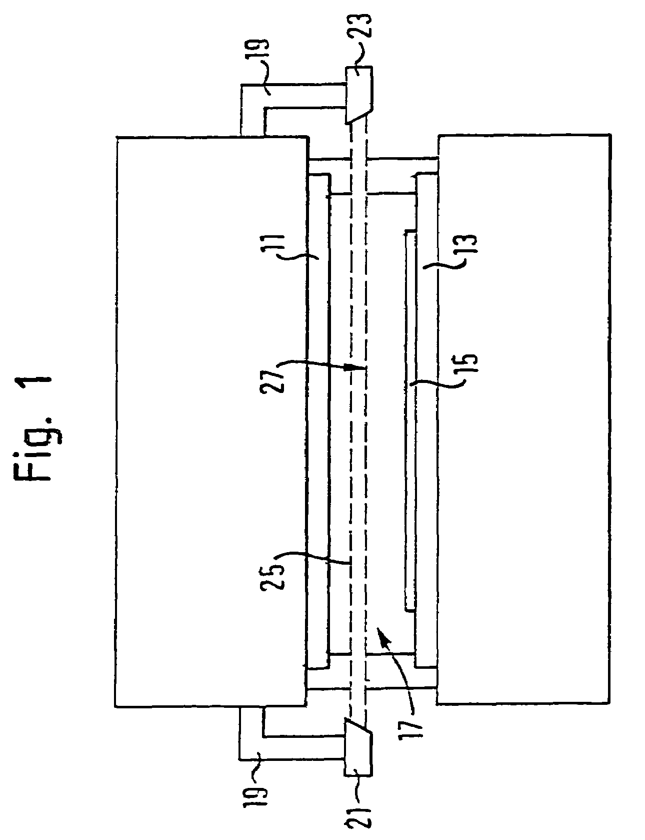
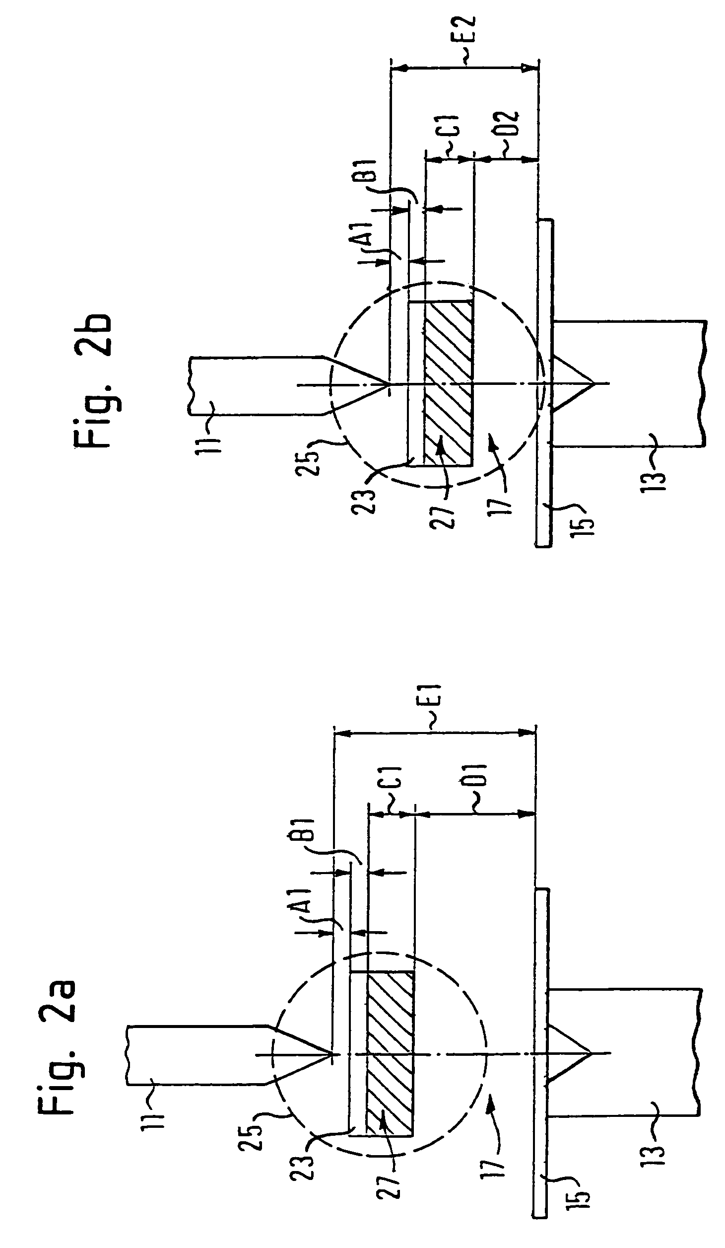
[0028]The stamping press shown in FIG. 1 has a top tool 11 which can be driven to make a working movement vertically downwardly toward a bottom tool 13 in order to bend a workpiece 15 lying on the bottom tool 13. An open gap 17 between the top tool 11 and the workpiece 15 is gradually closed during this working movement.

[0029]A respective holding arm 19 is provided at both sides of the top tool 11. The holding arms 19 carry a transmitter device 21 and a spatially resolving receiver device 23 which are parts of an optoelectronic sensor. The transmitter device 21 has a laser diode with an optical transmitter device (not shown in the Figures) which expands the transmitted light of the laser diode into a light ray 25. The receiver device 23 has a rectangular CMOS matrix receiver on which the light ray 25 acts.

[0030]The ligh...


PUM

PropertyMeasurementUnit
timeaaaaaaaaaa
transmissionaaaaaaaaaa
closing speedaaaaaaaaaa

Abstract

A method and an optoelectronic sensor are provided for ensuring the safety of a machine tool having a first tool part carrying out working movements in the direction of a second tool part. The sensor monitors a three-dimensional protected field between the tool parts of the machine tool. At the start of a working movement of a first tool part of the machine tool, the extent of the protected field in the direction of the working movement is smaller than the extent of the open gap between the tool parts. On a continued working movement, the extent of the protected field is continuously reduced and the protected field is held in the center of the open gap. Thereafter, on a further continued working movement, the extent of the protected field is maintained and the protected field is held in the center of the open gap. The sensor is finally deactivated.

Description

CROSS-REFERENCE TO RELATED APPLICATIONS[0001]This application is a National Stage of International Application No. PCT / EP2004 / 000926, filed Feb. 2, 2004, the disclosure of which, is incorporated herein by reference.FIELD OF THE INVENTION[0002]The present invention relates to ensuring the safety in use of machine tools, and more particularly to a safety method and optoelectronic sensor for ensuring the safety in use of a machine tool.BACKGROUND OF THE INVENTION[0003]The invention relates to a method for ensuring the safety in use of a machine tool having a first tool part carrying out working movements in the direction of a second tool part so that, in the course of these working movements, an open gap between the first tool part, on the one hand, and the second tool part or a workpiece to be machined, on the other hand, is gradually closed. In this process, an optoelectronic sensor monitors a three-dimensional protected field between the tool parts in that at least one light ray is ...

Claims


Application Information

Patent Timeline
Patent Type & Authority Patents(United States)
IPC IPC(8): G06M7/00B21D55/00H01J40/14F16P3/14G01V8/20
CPCF16P3/14F16P3/144G01V8/20B21D55/00
Inventor BRAUNE, INGOLFBERGBACH, ROLAND
Owner SICK AG
Why Eureka
Try Eureka