Axial fan

a technology of axial fan and fan body, which is applied in the direction of propulsive elements, motors, water-acting propulsive elements, etc., can solve problems such as fan operation problems

Active Publication Date: 2008-11-25
SPAL AUTOMOTIVE
View PDF8 Cites 16 Cited by
  • Summary
  • Abstract
  • Description
  • Claims
  • Application Information

AI Technical Summary

Benefits of technology

[0008]One aim of the invention is to provide an improved axial fan which is reliable even when operating in particularly difficult environmental conditions.
[0009]Another aim of the invention is to provide an improved axial fan which is simple and economical to produce.

Problems solved by technology

Axial fans of the type described above have several disadvantages, in particular if used with the cooling circuit of an agricultural vehicle.
In the most common working conditions for agricultural vehicles it is quite easy for water, sand and soil to build up in the air space between the electric motor, or the viscostatic coupling, and the impeller hub, creating a sludge that may cause problems with fan operation.

Method used


Image

  • Axial fan
  • Axial fan
  • Axial fan

Examples


Embodiment Construction

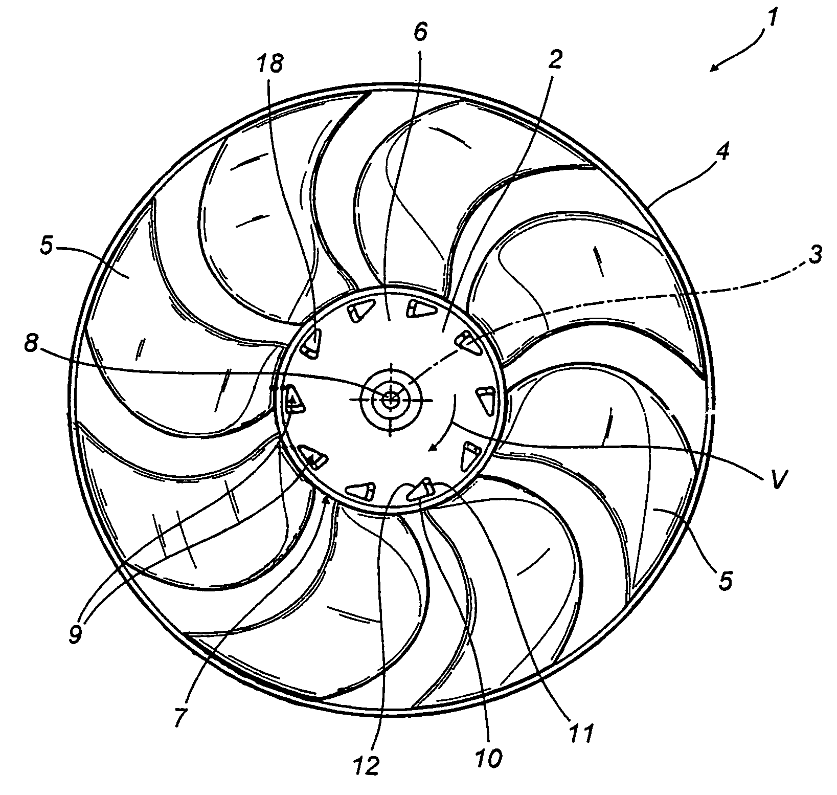
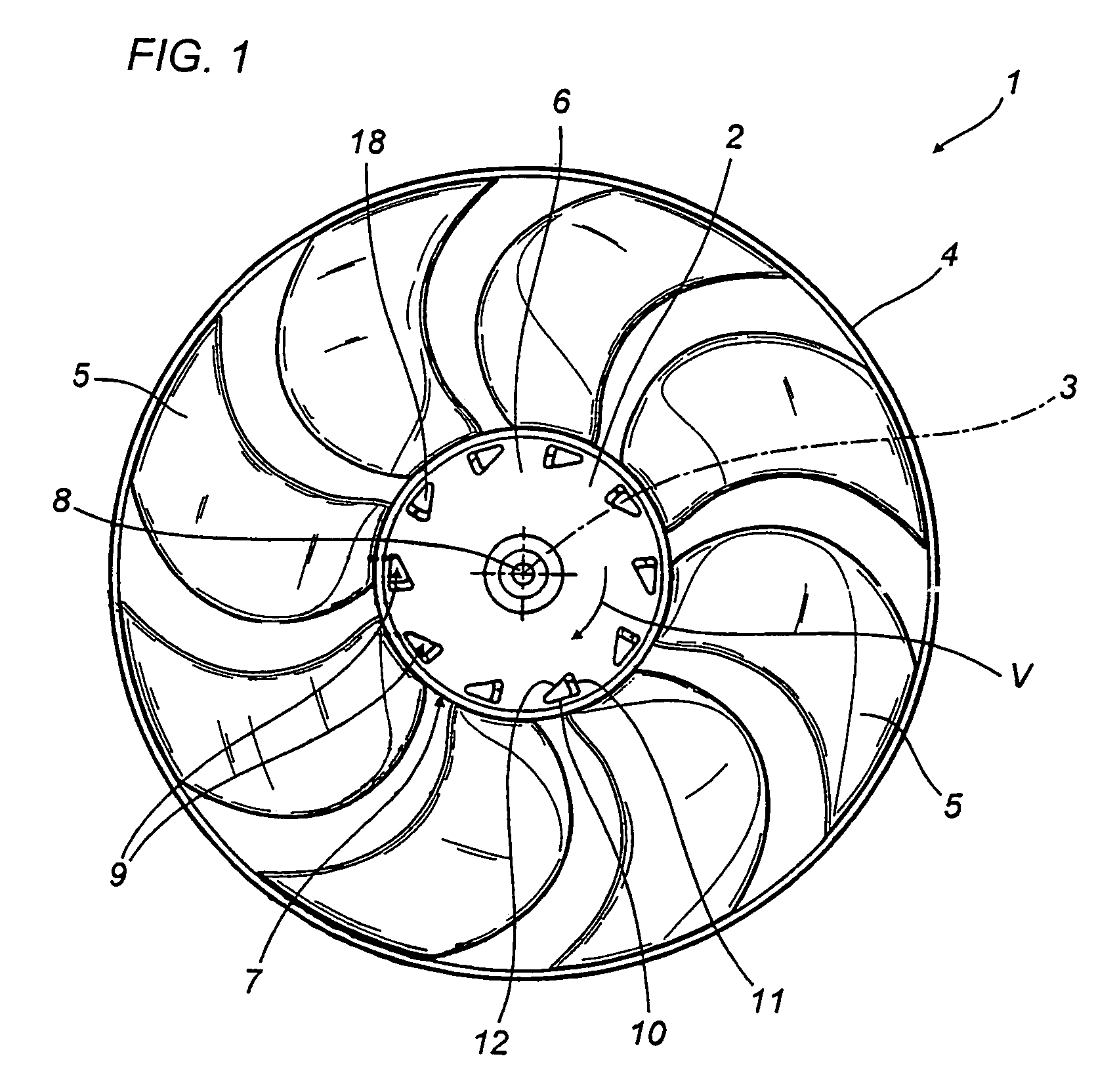
[0017]With reference to FIG. 1, the numeral 1 denotes an impeller of an axial fan which can be used to particular advantage with a cooling circuit (not illustrated) of an engine of an agricultural vehicle (also not illustrated).

[0018]The impeller 1 comprises a hollow central hub 2, extending substantially symmetrically about its central axis of rotation 3, a stiffening ring 4, centred on the axis 3 and surrounding the hub 2, and a plurality of blades 5, eight in the embodiment illustrated in FIG. 1, each extending between the hub 2 and the ring 4 in a direction transversal to the axis 3.

[0019]In the known way, the hub 2 is coaxially fixed to the shaft of an electric motor or any actuator device (not illustrated), which allows the impeller 1 and therefore the hub 2 to turn about the axis 3 in the direction V illustrated in FIGS. 1 and 2.

[0020]In the embodiment illustrated in FIG. 1, the blades 5 are positioned around the axis 3 and extend radially from the hub 2 with a profile and an...


PUM


Abstract

Described is an axial fan in which an impeller (1) comprises a hub (2), motor-powered so that it rotates about its own central axis (3) and a plurality of blades (5) extending from the hub (2) in directions transversal to the hub (2) axis of rotation (3); the hub having a cup shape and formed by a ring-shaped side wall (7) and a bottom wall (6) which has a plurality of long ribs (20) arranged in a radial direction and extending in height towards the hub (2) cavity, each of the ribs (20) abutting on the internal face of the ring-shaped side wall (7) and delimiting, together with said ring-shaped side wall, a corner area of the bottom wall (6) positioned in front of the rib (20) with reference to the hub (2) direction of rotation (V); each corner area having a through-hole (9) for discharging any debris, in particular water, sand, soil or sludge, from the hub (2) cavity to the outside of the hub (2) The through-holes (9) are evenly distributed along a circle centered on the hub (2) axis of rotation (3) and have a substantially triangular prismatic shape with a vertex wall (15) facing forwards according to the hub (2) direction of rotation (V).

Description

TECHNICAL FIELD[0001]The present invention relates to an axial fan.[0002]More precisely, the fan according to the present invention may be used in a system for cooling the engine of a vehicle, in particular an agricultural vehicle, to which the following description refers, without in any way limiting the scope of the invention.BACKGROUND ART[0003]Generally speaking, an engine cooling system comprises a radiator, which is part of a cooling circuit designed to dissipate into the environment the heat which a liquid circulating inside it carries away from the engine, and an axial fan, which generates a forced air flow through the radiator to promote the latter's dissipation of the heat.[0004]The fan may be driven by an electric motor, and comprises an impeller whose rotation is driven by the shaft of the electric motor. A thermostat which detects the temperature of the liquid in the cooling circuit controls activation of the electric motor, which keeps running until the temperature of ...

Claims


Application Information

Patent Timeline
Patent Type & Authority Patents(United States)
IPC IPC(8): F03B11/08F04D29/32F04D29/70
CPCF04D25/082F04D29/329F04D29/703F04D29/5806F04D29/32F04D29/70F04D29/00
Inventor SPAGGIARI, ALESSANDRO
Owner SPAL AUTOMOTIVE
Why Eureka
Try Eureka