
Amplitude error compensating device and quadrature skew error compensating device

a compensating device and amplitude technology, applied in the field of demodulation devices for use in digital radio communication, can solve problems such as amplitude errors or quadrature skew errors

Inactive Publication Date: 2008-11-25
SOCIONEXT INC
View PDF12 Cites 256 Cited by
  • Summary
  • Abstract
  • Description
  • Claims
  • Application Information

AI Technical Summary

Benefits of technology

[0033]According to the present invention, it is possible to achieve an amplitude / quadrature skew error compensating device which correctly performs amplitude / quadrature skew error correction without a malfunction. It is also possible to perform amplitude / quadrature skew error correction without occurrence of an error in signal power between before and after correction.

Problems solved by technology

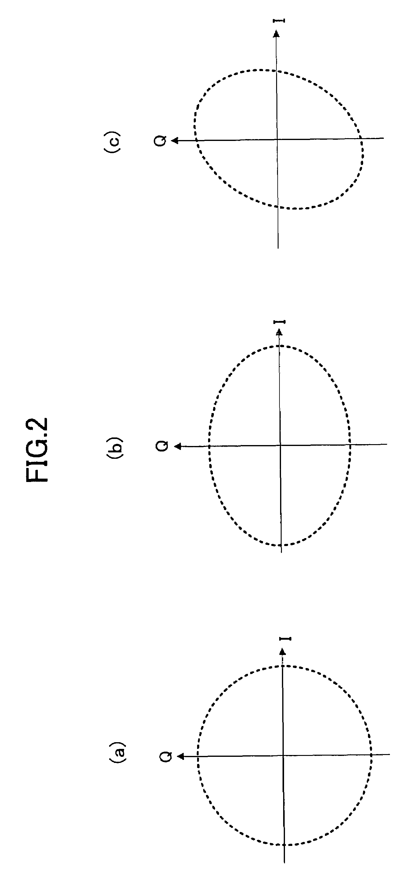
However, the analog quadrature demodulation section is affected by characteristic variations, temperature characteristics, voltage characteristics, and the like of the analog element, so that an amplitude error or a quadrature skew error occurs between the in-phase component and the quadrature component of the IQ signal.

Method used


Image

  • Amplitude error compensating device and quadrature skew error compensating device
  • Amplitude error compensating device and quadrature skew error compensating device
  • Amplitude error compensating device and quadrature skew error compensating device

Examples


first embodiment

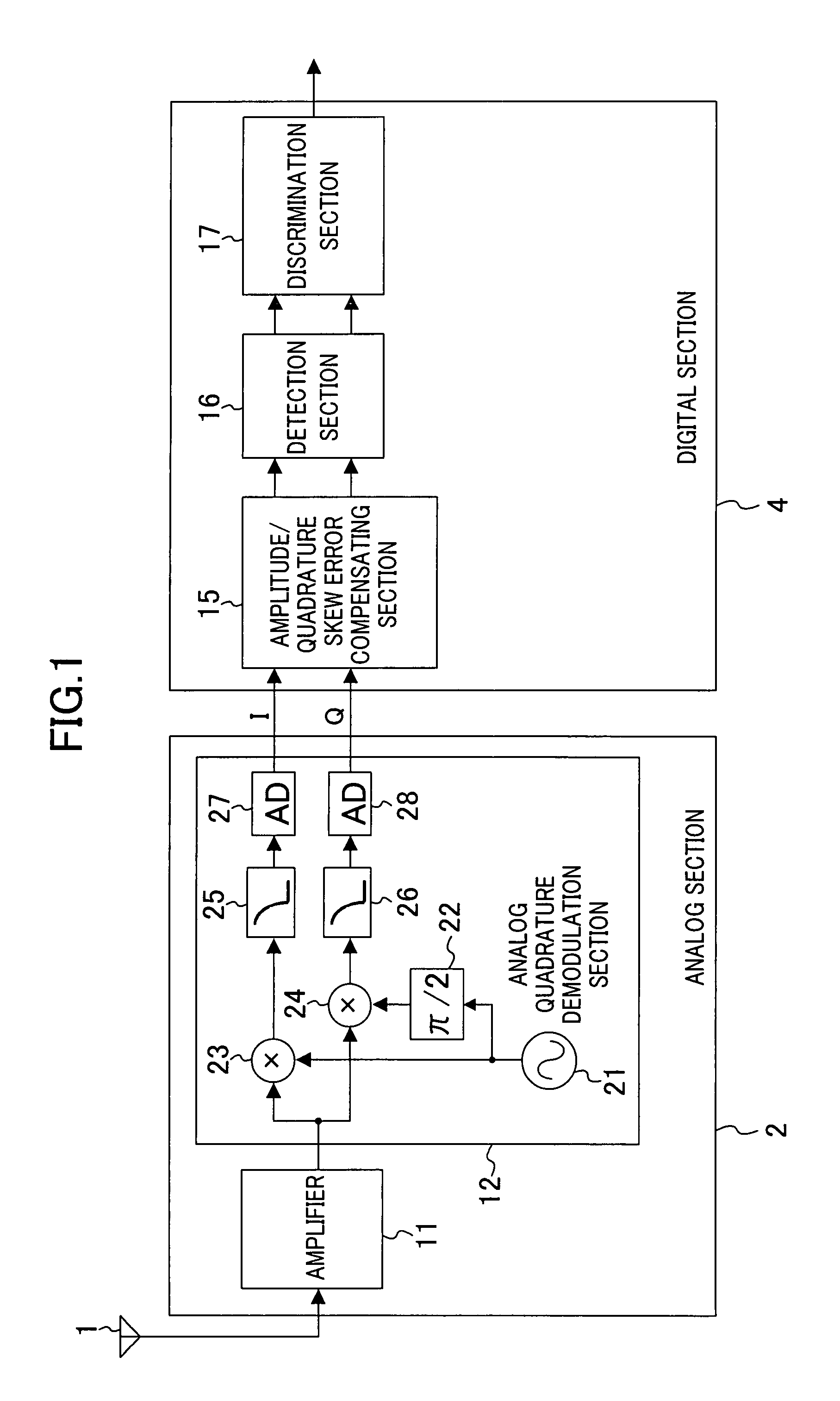
[0072]FIG. 1 is a block diagram of a demodulation device according to a first embodiment of the present invention. The demodulation device of FIG. 1 comprises an analog section 2 and a digital section 4. The analog section 2 comprises an amplification section 11 and an analog quadrature demodulation section 12. The digital section 4 comprises an amplitude / quadrature skew error compensating section 15, a detection section 16, and a discrimination section 17.

[0073]The amplification section 11 amplifies digital modulated waves received by an antenna 1, and outputs the amplified waves to the analog quadrature demodulation section 12. The analog quadrature demodulation section 12 subjects a signal output from the amplification section 11 to quadrature demodulation, and outputs a resultant signal to the amplitude / quadrature skew error compensating section 15. The quadrature-demodulated signal is a complex signal, which has an in-phase component (in-phase signal) I and a quadrature compone...

second embodiment

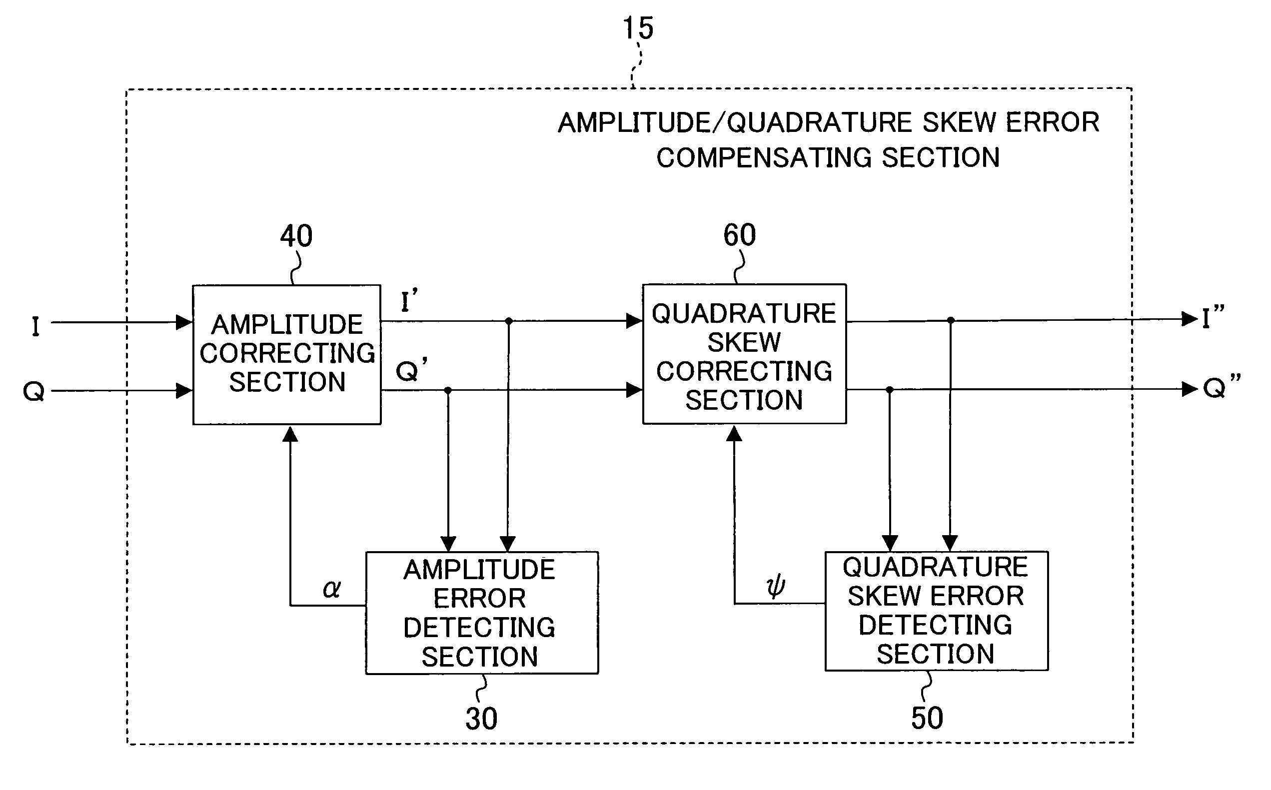
[0128]FIG. 11 is a block diagram illustrating an exemplary configuration of an amplitude / quadrature skew error compensating section 215 according to a second embodiment of the present invention. The amplitude / quadrature skew error compensating section 215 is used in place of the amplitude / quadrature skew error compensating section 15 in the demodulation device of FIG. 1. The amplitude / quadrature skew error compensating section 215 of FIG. 11 comprises a quadrature skew error detecting section 250 in place of the quadrature skew error detecting section 50, and further comprises a frequency offset detector 70, in the amplitude / quadrature skew error compensating section 15 of FIG. 3. The other parts are the same as those which have been described in the first embodiment, and are indicated by the same reference numerals and will not be described.

[0129]The frequency offset detector 70 detects a frequency offset with respect to carrier waves from an IQ signal output from the quadrature sk...

third embodiment

[0140]FIG. 13 is a block diagram illustrating an exemplary configuration of an amplitude / quadrature skew error compensating section 315 according to a third embodiment of the present invention. The amplitude / quadrature skew error compensating section 315 is used in place of the amplitude / quadrature skew error compensating section 15 in the demodulation device of FIG. 1. The amplitude / quadrature skew error compensating section 315 of FIG. 13 comprises an amplitude error detecting section 330 and a quadrature skew error detecting section 350 in place of the amplitude error detecting section 30 and the quadrature skew error detecting section 50, respectively, in the amplitude / quadrature skew error compensating section 15 of FIG. 3. The other parts are the same as those which have been described in the first embodiment, and are indicated by the same reference numerals and will not be described.

[0141]FIG. 14 is a block diagram illustrating an exemplary configuration of the quadrature ske...


PUM


Abstract

An amplitude error compensating device comprises an amplitude correcting section for performing amplitude correction with respect to an in-phase component and a quadrature component of a complex signal obtained by quadrature demodulation, based on amplitude error information, and outputting a resultant amplitude-corrected complex signal, and an amplitude error detecting section for obtaining the amplitude error information, depending on amplitudes of an in-phase component and a quadrature component of the amplitude-corrected complex signal. The amplitude error detecting section comprises a power difference calculating section for obtaining as a power error a difference in power between the in-phase component and the quadrature component of the amplitude-corrected complex signal, a rotation detecting section for detecting a rotation of a signal point of the amplitude-corrected complex signal, an error information control section for outputting the power error when a rotation of the signal point has been detected, and 0 when a rotation of the signal point has not been detected, and a smoothing section for smoothing an output of the error information control section, and outputting the result as the amplitude error information.

Description

RELATED APPLICATIONS[0001]This application is the U.S. National Phase under 35 U.S.C. § 371 of International Application No. PCT / JP2006 / 310887, filed on May 31, 2006, which in turn claims the benefit of Japanese Application No. 2005-169624, filed on Jun. 9, 2005, the disclosures of which Applications are incorporated by reference herein.TECHNICAL FIELD[0002]The present invention relates to a demodulation device for use in digital radio communication. More particularly, the present invention relates to a device for detecting and correcting an amplitude error or a quadrature skew error between an in-phase component and a quadrature component of a complex signal obtained by quadrature demodulation in an analog quadrature demodulation section.BACKGROUND ART[0003]Digital modulation schemes for use in digital radio communication include digital phase modulation schemes (e.g., BPSK (Binary Phase Shift Keying), QPSK (Quadrature Phase Shift Keying), 8PSK (Phase Shift Keying)), QAM (Quadratur...

Claims


Application Information

Patent Timeline
Patent Type & Authority Patents(United States)
IPC IPC(8): H04L27/38H04L27/22
CPCH04L27/3863
Inventor TAKANO, HARUKASOGA, SHIGERU
Owner SOCIONEXT INC
Learn More