Image forming apparatus, method of controlling the same, program, storage medium, printing system, and method suitable for the printing system

Active Publication Date: 2008-11-25
CANON KK
View PDF4 Cites 14 Cited by
  • Summary
  • Abstract
  • Description
  • Claims
  • Application Information

AI Technical Summary

Benefits of technology

[0006]It is therefore an object of the present invention to provide an image forming apparatus, a method of controlling the same, a printing system and a method suitable for the printing system, which are capable of realizin

Problems solved by technology

According to the trial printing function, however, all of read images are subjected to processing, and all of pages included in each copy are subjected to printing, and hence, time and supplies such as toners and sheets may be unnecessarily consumed.
For example, the trial printing funct

Method used


Image

  • Image forming apparatus, method of controlling the same, program, storage medium, printing system, and method suitable for the printing system
  • Image forming apparatus, method of controlling the same, program, storage medium, printing system, and method suitable for the printing system
  • Image forming apparatus, method of controlling the same, program, storage medium, printing system, and method suitable for the printing system

Examples


first embodiment

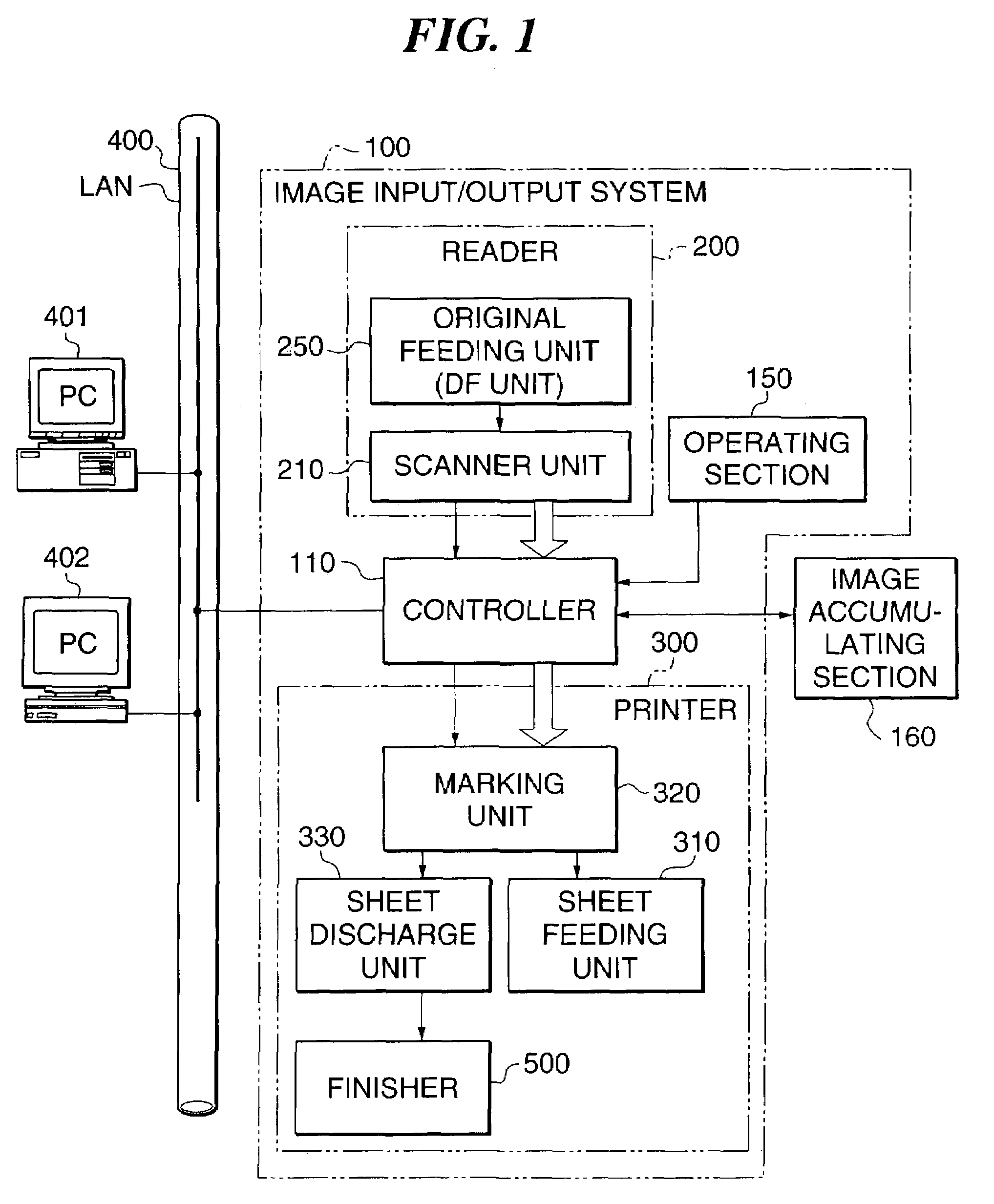
[0076]FIG. 1 is a block diagram showing the entire arrangement of an image input / output system as a printing system according to the present invention.

[0077]As shown in FIG. 1, an image input / output system 100 is comprised of a reader 200 that optically reads an image on an original and converts the read image into image data; a printer 300 that feeds a sheet, prints image data as a visual image on the sheet, and discharges the sheet from the printer 300; and a controller 110 that controls the reader 200 and the printer 300.

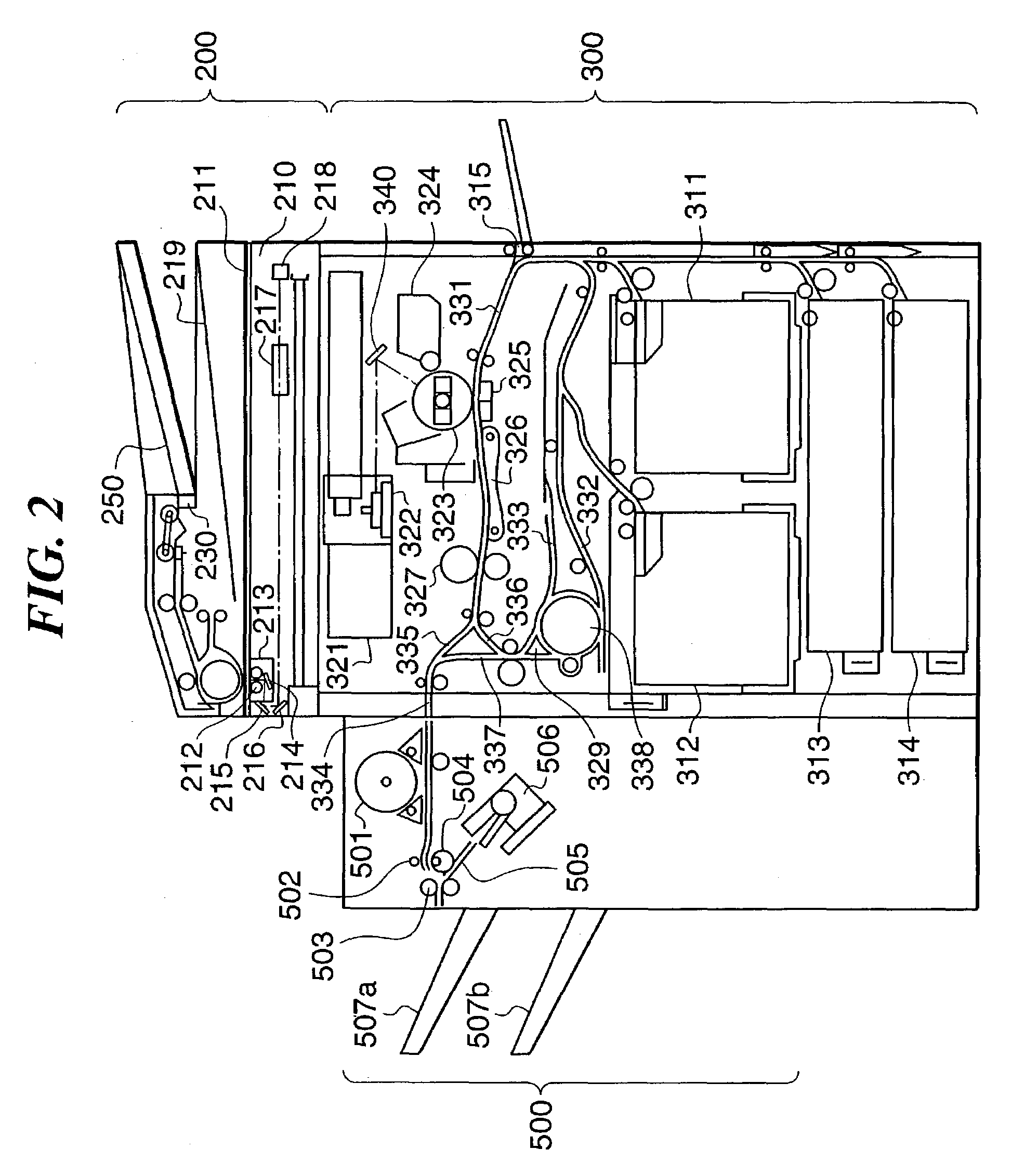
[0078]The reader 200 is comprised of an original feeding unit (DF unit) 250 that feeds an original, and a scanner unit 210 that reads an original.

[0079]The printer 300 is comprised of a sheet feeding unit 310 including different types of sheet cassettes, a marking unit 320 that transfers and fixes image data on a sheet, a sheet discharge unit 330 that outputs a sheet with an image printed thereon from the printer 300, and a finisher unit 500 that performs staplin...

second embodiment

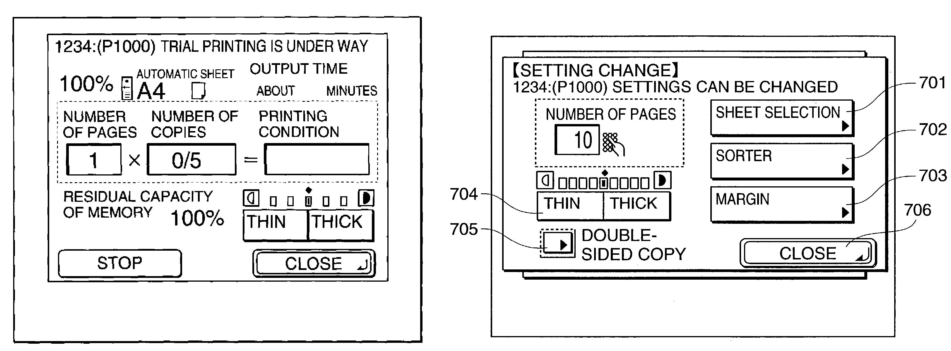
[0176]A description will now be given of the present invention with reference to FIGS. 25 to 32. FIGS. 25 and 26 are flow charts showing the procedure for providing idling control in an image input / output system according to the present embodiment, FIGS. 27A-27B are flow chart showing the procedure for carrying out sequential reading in FIG. 26, FIG. 28 is a view showing an example of a screen displayed on the operating section 150 upon shift to an intermediate state of sequential reading in a step S265 in FIGS. 27A-27B, FIG. 29 is a view showing an example of an original type setting popup displayed upon depression of an original type key in FIG. 28, FIG. 30 is a flow chart showing the procedure for carrying out automatic page calculation, FIG. 31A is a view showing an example of read originals whose image qualities have been changed, the view being useful in explaining the details of processing in a step S282 in FIG. 30, FIG. 31B is a view showing an example of trial copying in th...


PUM


Abstract

There is provided an image forming apparatus capable of realizing a trial printing function that minimizes unnecessary consumption of time and supplies. Images that are inputted are accumulated in a memory. An output mode is set and a setting is made as to whether trial printing is to be carried out in the output mode or not. A CPU provides control to read out a corresponding image from the memory according to the set output mode and form the readout image on a sheet. When it is determined that the trial printing is to be carried out during image formation according to the set output mode, the CPU provides control to set the number of trial print pages according to predetermined conditions and carry out the trial printing for the set number of trial print pages.

Description

BACKGROUND OF THE INVENTION[0001]1. Field of the Invention[0002]The present invention relates to an image forming apparatus capable of performing trial printing, a method of controlling the same, a program for implementing the method, and a storage medium storing the program as well as a printing system and a method suitable for the printing system.[0003]2. Description of the Related Art[0004]In recent years, a digital copying machine having a plurality of functions has been developed. The digital copying machine reads an image on an original by a CCD (Charged Coupled Device) and converts it into a digital signal, and performs various processing on the digital signal and then converts it into a laser signal to record an image on a sheet by electrophotography. The digital copying machine also temporarily stores the read image data in an image memory such as a hard disk and reads out the image data to form an image. By repeating this sequence a plurality of times, the digital copying ...

Claims


Application Information

Patent Timeline
IPC IPC(8): G06F15/00G06F3/12H04N1/00
CPCH04N1/00002H04N1/00015H04N1/00031H04N1/00047H04N1/0005H04N1/00063
Inventor KUBOKI, KEIJU
Owner CANON KK
Why Eureka
Try Eureka