Systems and methods for ARC energy regulation

a technology of energy regulation and system, applied in the direction of discharge tube/lamp details, instruments, heat measurement, etc., can solve the problem of inefficient waste of energy for some ionization events

Active Publication Date: 2008-11-25
AXON ENTERPRISE INC
View PDF9 Cites 15 Cited by
  • Summary
  • Abstract
  • Description
  • Claims
  • Application Information

AI Technical Summary

Problems solved by technology

Using a fixed maximum amount of energy for every ionization can lead only to inefficient waste of energy for some ionization events.

Method used


Image

  • Systems and methods for ARC energy regulation
  • Systems and methods for ARC energy regulation
  • Systems and methods for ARC energy regulation

Examples


Embodiment Construction

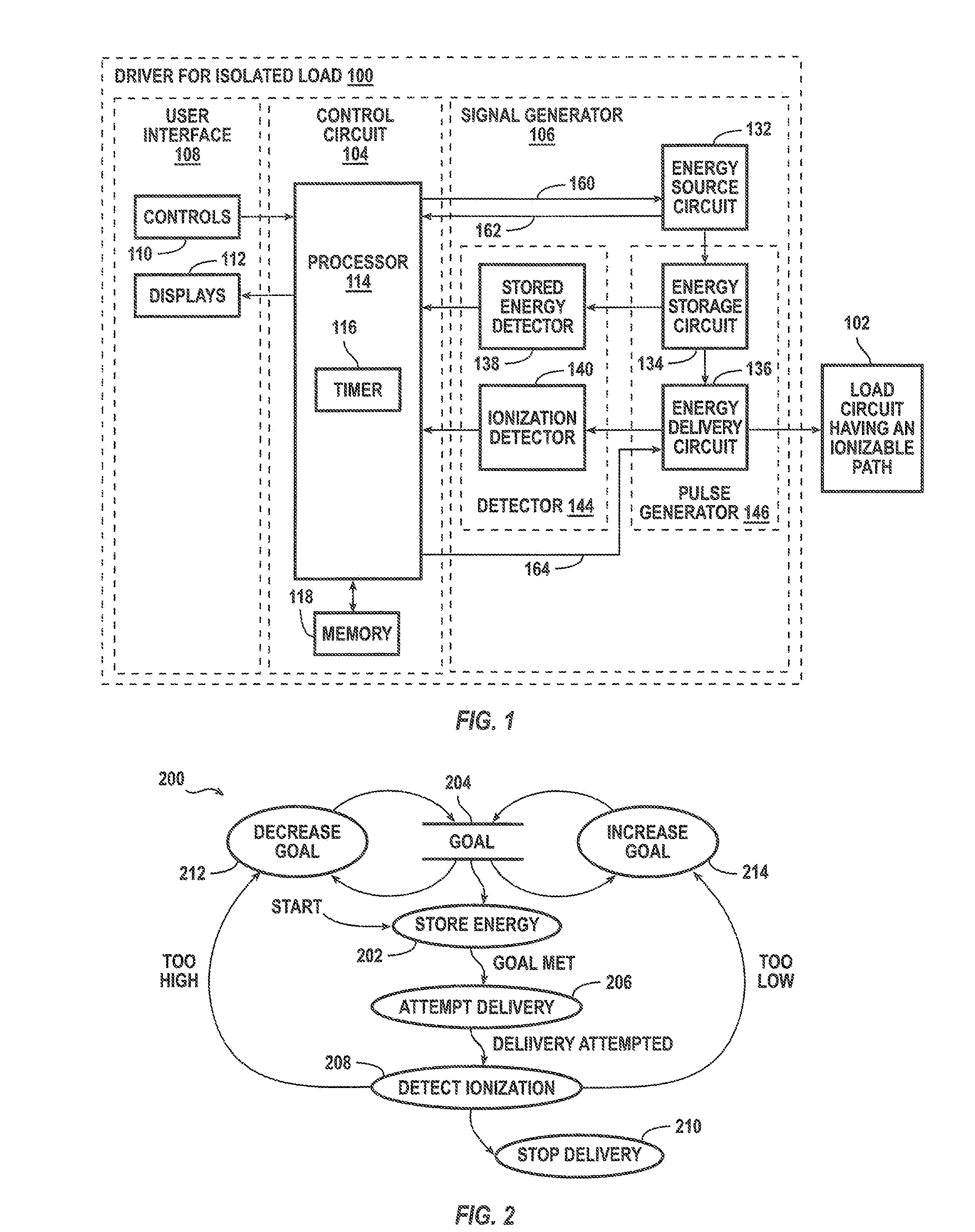
[0014]To provides a current through a load, a circuit must exist through the load. Ionization may be necessary to form such a circuit. The circuit exists while ionization is maintained. A relatively high voltage is generally required from a drive circuit to accomplish ionization of a particular path. When the load presents a relatively low impedance to the driver, the relatively high voltage of the driver impressed across the relatively low impedance of the load may cause a relatively high power to be dissipated in the ionized path and the load. When the insulating properties of the path vary, a lower voltage may be sufficient to accomplish ionization. Using the relatively high voltage when a lower voltage may be sufficient contributes to unnecessary power consumption. Power consumption may be reduced according to various aspects of the present invention.

[0015]Applications for drive circuits according to various aspects of the present invention may includes power distribution, commu...


PUM


Abstract

A driver provides a current through a load circuit that includes an ionizable path. The driver includes an energy sourcing circuit, an ionization detector, a controller, and a pulse generator. The controller determines, in response to the detector and by trial and error, a respective quantity of energy for each pulse of a plurality of pulses to be generated. For each pulse of the plurality, the pulse generator receives the respective quantity of energy from the energy sourcing circuit, provides in response to the quantity of energy a respective voltage to ionize the ionization path, and provides the current through the load circuit.

Description

FIELD OF THE INVENTION[0001]Embodiments of the present invention relate to systems and methods for arc energy regulation.BACKGROUND OF THE INVENTION[0002]An electric arc formed between a pair of conductors that are separated by an otherwise insulating gas may be designed to provide light, heat, sound, or radio frequency signals. By providing heat, the arc may be used to ignite the gas, for example for producing light, heat or propulsion. In other applications for an electric arc, the arc may be designed to complete a circuit for current to flow through the arc and through a load. A circuit that causes an arc to form and thereafter supplies a current through the load is a drive circuit, as opposed to merely an igniter circuit, in part because it impresses across the conductors a voltage high enough to cause ionization of the gas and then provides a current through the arc and through the load. Prior to ionization, the insulating effect of the gas prevents current from flowing through...

Claims


Application Information

Patent Timeline
Patent Type & Authority Patents(United States)
IPC IPC(8): H01T23/00
CPCF41B15/04F41H13/0006F41H13/0012F42B12/36
Inventor BRUNDULA, STEVEN N. D.
Owner AXON ENTERPRISE INC
Why Eureka
Try Eureka