Exhaust gas purification system of internal combustion engine

a technology of exhaust gas purification system and internal combustion engine, which is applied in the direction of position/direction control, special data processing applications, and dispersed particle filtration, etc. it can solve the problem of low uniformity of flow velocity distribution, and achieve the effect of avoiding untimely regeneration of particulate filters, uniform temperature distribution of particulate filters, and low flow velocity distribution

Active Publication Date: 2008-12-02
DENSO CORP
View PDF15 Cites 28 Cited by
  • Summary
  • Abstract
  • Description
  • Claims
  • Application Information

AI Technical Summary

Benefits of technology

[0010]It is therefore an object of the present invention to provide an exhaust gas purification system of an internal combustion engine capable of precisely determining a deposited state of exhaust particulate matters in consideration of a flowing state of exhaust gas in a particulate filter.
[0012]Even when the mass of the gas is the same, the volume thereof differs if the temperature differs. Therefore, when the uniformity of the temperature distribution in the particulate filter is low, uniformity of flow velocity distribution is also low. When the uniformity of the measured temperature distribution is low, the determination of the deposited state of the exhaust particulate matters is prohibited. Thus, the deposited state of the exhaust particulate matters can be determined properly. As a result, the regeneration of the particulate filter at inappropriate timing can be avoided.

Problems solved by technology

Therefore, when the uniformity of the temperature distribution in the particulate filter is low, uniformity of flow velocity distribution is also low.

Method used


Image

  • Exhaust gas purification system of internal combustion engine
  • Exhaust gas purification system of internal combustion engine
  • Exhaust gas purification system of internal combustion engine

Examples


first embodiment

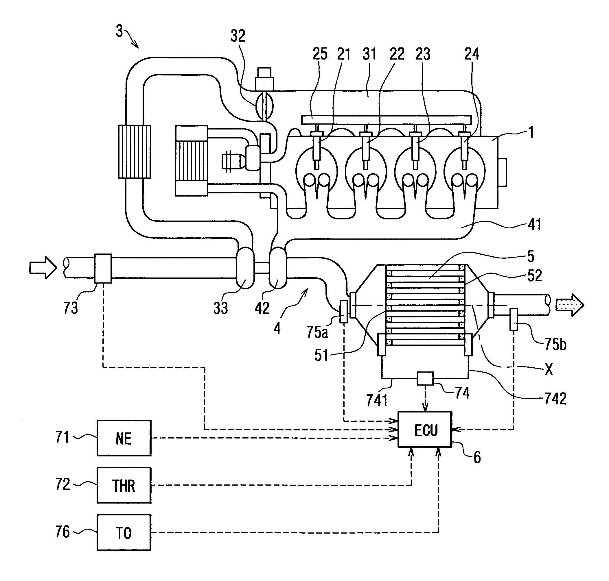
[0028]Referring to FIG. 1, a diesel engine having an exhaust gas purification system according to a first embodiment of the present invention is illustrated. An engine main body 1 includes multiple (four, in the present embodiment) cylinders. Injectors 21, 22, 23, 24 mounted to the respective cylinders on a one-on-one basis inject fuel into the cylinders. The fuel is supplied to the injectors 21-24 from a common rail 25, which is common to the injectors 21-24. Gas for forming a mixture gas with the fuel is supplied into the cylinders from an intake manifold 31, which provides a downstream portion of an intake passage 3. Exhaust gas generated by combusting the mixture gas is discharged from the respective cylinders to an exhaust manifold 41, which provides an upstream portion of an exhaust passage 4. A turbine 42 of a turbocharger and a particulate filter (a diesel particulate filter: DPF) 5 are disposed in the exhaust passage 4.

[0029]The DPF 5 is made of heat-resistant ceramics such...

second embodiment

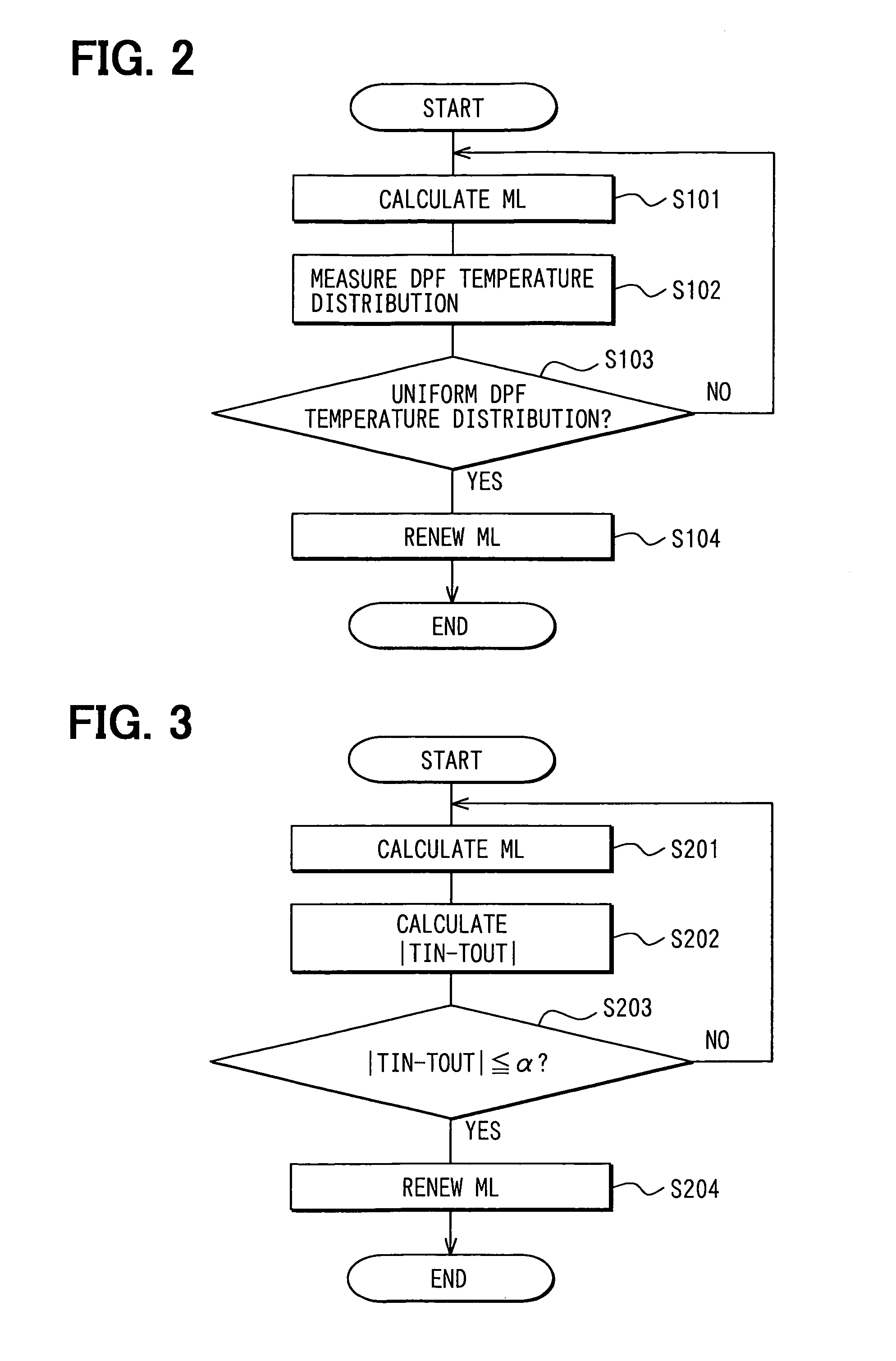
[0045]Next, processing for renewing a PM deposition quantity ML performed by an ECU of an exhaust gas purification system of an internal combustion engine according to a second embodiment of the present invention will be explained based on a flowchart shown in FIG. 3.

[0046]In Step S201, the PM deposition quantity ML is measured as in the first embodiment. Then, in Step S202, a difference (an absolute value) between the DPF inlet gas temperature TIN and the DPF outlet gas temperature TOUT is calculated as a value indicating a range of the temperature distribution in the DPF 5. The DPF inlet gas temperature TIN and the DPF outlet gas temperature TOUT are respectively sensed by the exhaust gas temperature sensors 75a, 75b. The DPF inlet gas temperature TIN can be regarded as the temperature of the most upstream part of the DPF 5. The DPF outlet gas temperature TOUT can be regarded as the temperature of the most downstream part of the DPF 5, which is distant from the most upstream part ...

third embodiment

[0048]Next, processing for renewing a PM deposition quantity ML performed by an ECU of an exhaust gas purification system of an internal combustion engine according to a third embodiment of the present invention will be explained based on FIGS. 4 to 12.

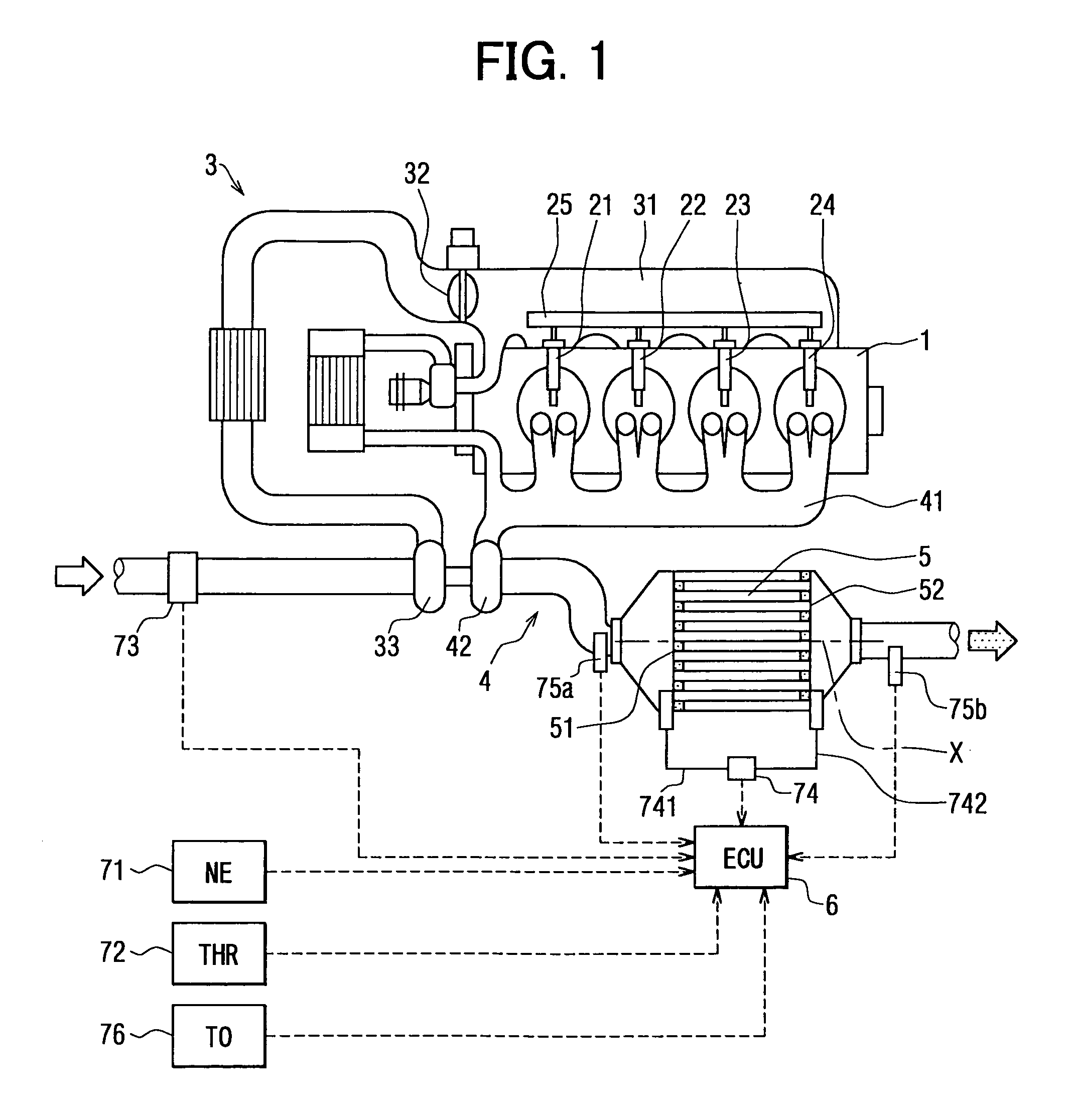
[0049]First, the PM deposition quantity ML is calculated in Step S301. Then, in Step S302, the temperature distribution in the DPF 5 is measured with the use of the exhaust gas temperature sensor 75a, and a difference between the maximum value and the minimum value of the temperatures in the DPF 5 is estimated based on the result of the measurement of the temperature distribution.

[0050]More specifically, in Step S302, temperatures at multiple points inside the DPF 5 are estimated based on the DPF inlet gas temperature TIN. As shown in FIG. 5, the temperatures are estimated at three estimation points B, C, D on a central line X of the DPF 5 extending along the direction of the flow of the exhaust gas. The estimated temperatures at the ...


PUM

PropertyMeasurementUnit
temperaturesaaaaaaaaaa
temperatureaaaaaaaaaa

Abstract

An exhaust gas purification system determines a deposited state of particulate matters based on a differential pressure across a diesel particulate filter (DPF) sensed by a differential pressure sensor. An electronic control unit (ECU) of the system prohibits the determination of the deposited state of the particulate matters, which is performed based on the differential pressure, when uniformity of temperature distribution inside the DPF is low. The ECU estimates temperatures at multiple points inside the DPF distant from an inlet along a direction of a flow of exhaust gas based on the temperature at the inlet sensed by an exhaust gas temperature sensor disposed immediately upstream of the DPF. The ECU determines the uniformity of the temperature distribution inside the DPF based on a range of the temperatures at the multiple points.

Description

CROSS REFERENCE TO RELATED APPLICATION[0001]This application is based on and incorporates herein by reference Japanese Patent Applications No. 2004-4910 filed on Jan. 13, 2004 and No. 2004-297379 filed on Oct. 12, 2004.BACKGROUND OF THE INVENTION[0002]1. Field of the Invention[0003]The present invention relates to an exhaust gas purification system of an internal combustion engine having a particulate filter. Specifically, the present invention relates to an exhaust gas purification system of an internal combustion engine capable of performing regeneration of a particulate filter at proper timing.[0004]2. Description of Related Art[0005]In recent years, reduction of exhaust emission of internal combustion engines installed in automobiles and the like has been required. Specifically, in a compression ignition diesel engine whose fuel is light oil, it is necessitated to eliminate not only gas such as carbon monoxide, hydrocarbon and nitrogen oxides, but also exhaust particulate matter...

Claims


Application Information

Patent Timeline
Patent Type & Authority Patents(United States)
IPC IPC(8): F01N3/00G01N19/10B01D46/42F02D45/00B01D53/94F01N3/02F01N3/023F01N9/00F01N11/00F02B29/04F02B37/00F02M25/07G06F19/00
CPCF01N9/002F01N11/002F02D41/1448F01N2560/06F01N2900/0421F02B29/0406F02B37/00F02D2200/0802F02D2200/0804F02D2200/0812F02M25/0707F02M25/0727Y02T10/47F02M26/05F02M26/23Y02T10/40
Inventor YAHATA, SHIGETOSAITO, MAKOTOTOCHIKAWA, KAZUHARU
Owner DENSO CORP
Why Eureka
Try Eureka