Expandable bracket assembly for a removable car shaker

a technology of expandable brackets and shakers, which is applied in the direction of washstands, scaffold accessories, lighting support devices, etc., can solve the problems of loose connection, inability to transmit full vibratory force, and general jamming of materials,

Active Publication Date: 2008-12-02
VIBCO
View PDF6 Cites 3 Cited by
  • Summary
  • Abstract
  • Description
  • Claims
  • Application Information

AI Technical Summary

Benefits of technology

[0010]The present invention may be briefly described as an expandable vibrator bracket for attaching a car-shaker vibrator to a female receptacle attached to a railroad car to be vibrated. The expandable bracket includes: a vibrator mounting member, a leg member, and a wedge base member. The vibrator mounting member is configured for supporting the vibrator. The wedge base member further includes a first end, a second end, a first side, and a second side. The wedge plate includes an attaching end, a distal end, an interior side and an exterior side. The attaching end is arrayed to be coupled to the first end of the wedge base member for a

Problems solved by technology

Usually, transporting the material from one site to another results in compaction thereof.
After compaction, the materials generally are jammed and do not flow easily upon the opening of the hopper car discharge gate or gates.
Any looseness in the connection will not allow the full vibratory force to be transmitted into the hopper car.
Furthermore excessive looseness will most likely result in further wear of the male portion and/or the female portion.
It is probably not desirable or economically feasible to remove

Method used


Image

  • Expandable bracket assembly for a removable car shaker
  • Expandable bracket assembly for a removable car shaker
  • Expandable bracket assembly for a removable car shaker

Examples


second embodiment

DETAILED DESCRIPTION OF THE SECOND EMBODIMENT

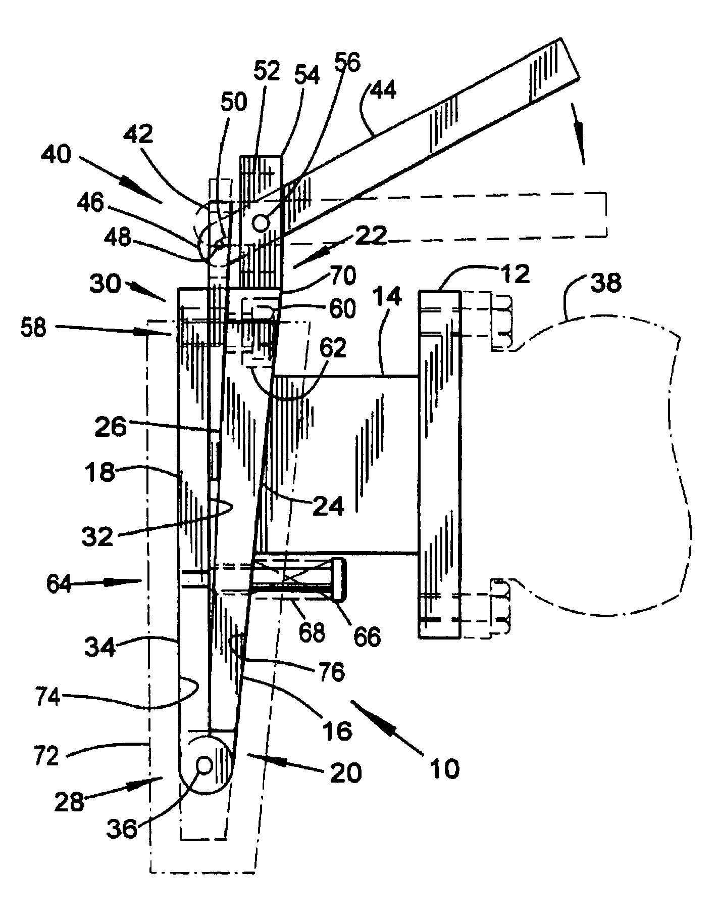
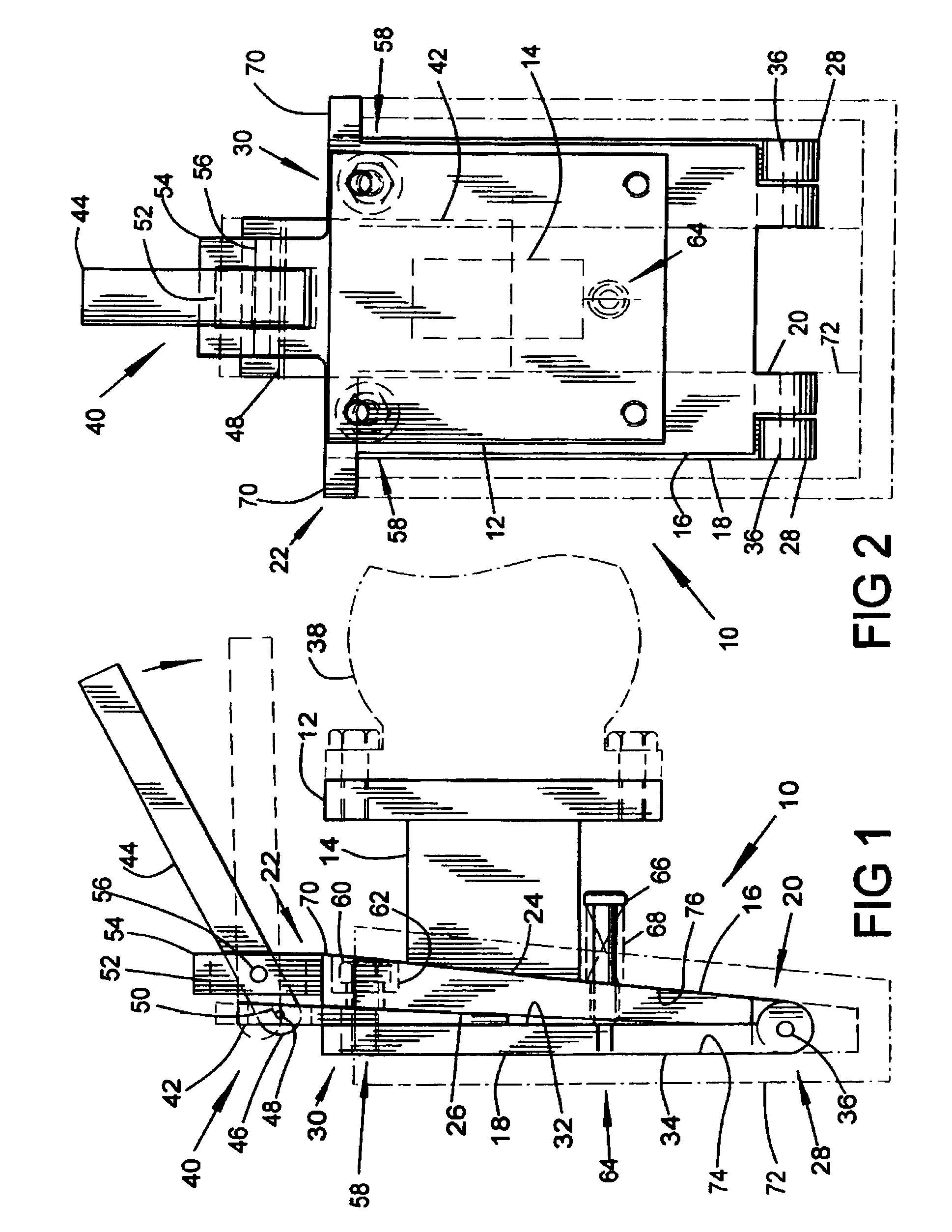
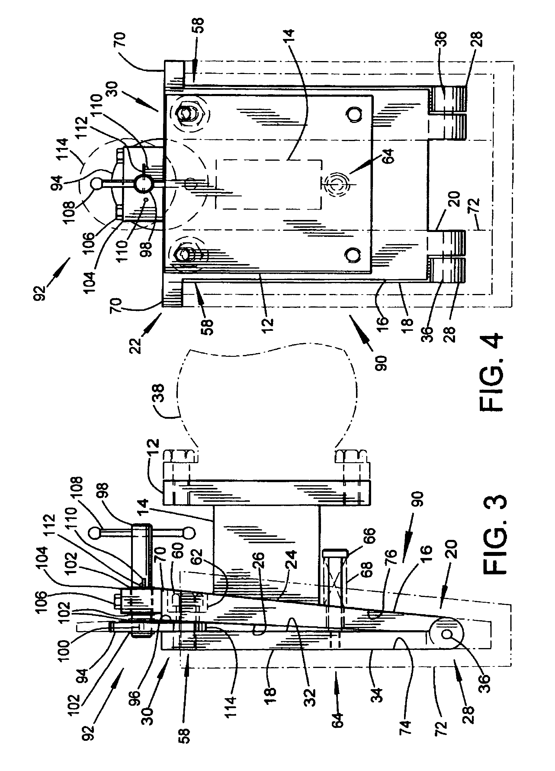
[0027]Referring now in particular to FIGS. 3 and 4, the second embodiment of the expandable male bracket portion is generally identified as 90. This second embodiment of the expandable male bracket portion 90 is very similar to the expandable male bracket portion 10 and includes the vibrator mounting member 12, the leg member 14, the wedge base member 16, and the wedge plate 18 that are couple together as previously described above.

[0028]The second embodiment of the expandable male bracket portion 90 replaces the linear spreader member 40 with a rotary spreader member 92. The rotary spreader member 92 includes a disc member 94 that has at least one tapered face 96 forming a rotating wedge having a peripheral edge 114 that is thinner than its central or hub portion. The disc member 94 is removably mounted and retained to a shaft 98 in an eccentric fashion by and with suitable retaining means. One non-limiting example of a suitable retainin...

third embodiment

DETAILED DESCRIPTION OF THE THIRD EMBODIMENT

[0030]Referring now in particular to FIGS. 5 and 6, the third embodiment of the expandable male bracket portion is generally identified as 120. This third embodiment of the expandable male bracket portion 120 is very similar to the expandable male bracket portion 10 and / or 90 in that it includes the vibrator mounting member 12, the leg member 14, the wedge base member 16, and the wedge plate 18 that are couple together as described above in the first embodiment. The primary difference between this expandable male bracket portion 120 and the previously described male bracket portion 10 and / or the male bracket portion 90 is that the spreader member is in the form of at least one biasing member 122 that is mounted between the wedge base member 16 and the wedge plate 18. Some non-limiting examples of a biasing member 122 are a heavy-duty compression spring, a die spring, urethane compression spring and the like. One end of each biasing member ...

fourth embodiment

DETAILED DESCRIPTION OF THE FOURTH EMBODIMENT

[0033]Referring now in particular to FIGS. 7 and 8, the fourth embodiment of the expandable male bracket portion is generally identified as 150. This fourth embodiment of the expandable male bracket portion 150 is very similar to the expandable male bracket portion 120 in that it includes the vibrator mounting member 12, the leg member 14, the wedge base member 16, and the wedge plate 18. The wedge base member 16 and the wedge plate 18 are coupled together as described above in the first embodiment 10. Similar to the third embodiment 120, the wedge base member 16 and the wedge plate member 18 are urged apart by the spreader member in the form of at least one biasing member 122. The type, number and mounting of the biasing members 122 are described above in connection with the third embodiment 120.

[0034]The main difference between the fourth embodiment 150 and the third embodiment 120 of expandable male bracket assemblies is in the expansi...


PUM


Abstract

An expandable vibrator bracket for attaching a car-shaker vibrator to a female receptacle attached to a railroad car to be vibrated. The expandable bracket includes: a vibrator mounting member, a leg member, and a wedge base member. The vibrator mounting member supports the vibrator. The wedge base member further includes a first end, a second end, a first side, and a second side. The wedge plate includes an attaching end, a distal end, an interior side and an exterior side. The attaching end is coupled to the first end of the wedge base member for allowing the distal end to selectively move with respect to the second end of the wedge base member when acted upon by a spreading or expanding force. The second side of the wedge base member and the exterior side of the wedge plate simultaneously abut opposite interior surfaces of the female receptacle during selective urging by the spreading force for holding the expandable vibrator bracket in the female receptacle. The spreading force may include a linear type of wedge, a rotary wedge, springs. The subsequent removal of the spreading or expanding force allows for the removal of the collapsed vibrator bracket from the female receptacle.

Description

CROSS REFERENCE TO RELATED APPLICATION[0001]Not ApplicableSTATEMENT REGARDING FEDERALLY SPONSORED RESEARCH OR DEVELOPMENT[0002]Not ApplicableBACKGROUND OF THE INVENTION[0003]1. Field of the Invention[0004]With regard to the classification of art, this invention is believed to be found in the general class for Supports and more particularly to those subclasses pertaining to the removable mounting of a car shaker vibrator to a railroad car.[0005]2. Description of Related Art[0006]Railroad hopper cars are used to transport various types of material such as; coal, cement, chemicals, flour, grains and the like. Usually, transporting the material from one site to another results in compaction thereof. After compaction, the materials generally are jammed and do not flow easily upon the opening of the hopper car discharge gate or gates. Generally a car-shaker vibrator is removably attached to the railroad hopper car for breaking loose the jammed material and maintaining its flow until the c...

Claims


Application Information

Patent Timeline
IPC IPC(8): E04G5/06
CPCB65D88/66B65G67/24
Inventor WADENSTEN, THEODORE S.
Owner VIBCO
Why Eureka
Try Eureka