Particulate mixer having paddles of different lengths

a technology of paddles and mixers, which is applied in the direction of mixers rotary stirring mixers, mixing/kneading with horizontally mounted tools, etc. it can solve the problems of significant damage, poor applicability of mixing particulates having a significant specific gravity variation or a significant particle size variation, and affecting the quality of the product. , to achieve the effect of less pollutant, less residue, and easy cleaning and washing with water

Active Publication Date: 2008-12-02
TSUKASA
View PDF8 Cites 15 Cited by
  • Summary
  • Abstract
  • Description
  • Claims
  • Application Information

AI Technical Summary

Benefits of technology

[0011]The particulate mixer of the invention has the following advantageous characteristics:
[0012](1) The drum has the truncated cone-shaped inclined faces on its both ends to allow the gravitational breakdown of the particulate. The inner paddles and the outer paddles have different whole lengths in the radial direction. This gives the different paddle circumferential velocities to form a three-dimensional chaotic mixing flow of the particulate over the whole area of the particulate mixer and thereby widen the mixing flow area.
[0017](6) The particulate mixer shortens the discharge time of the particulate.

Problems solved by technology

This leads to some disadvantages: a relatively monotonous mixing flow in a limited mixing flow area, a relatively long mixing time and significant damages on tea leaves or similar particulate, and poor applicability for mixing particulate having a significant specific gravity variation or a significant particle size variation.
This leads to other disadvantages: residue and pollutant in the bottom corners on both sides of the drum; water accumulation and difficulty in cleaning and water washing in the bottom corners on both sides of the drum; and a relatively long discharge time.

Method used


Image

  • Particulate mixer having paddles of different lengths
  • Particulate mixer having paddles of different lengths
  • Particulate mixer having paddles of different lengths

Examples


Embodiment Construction

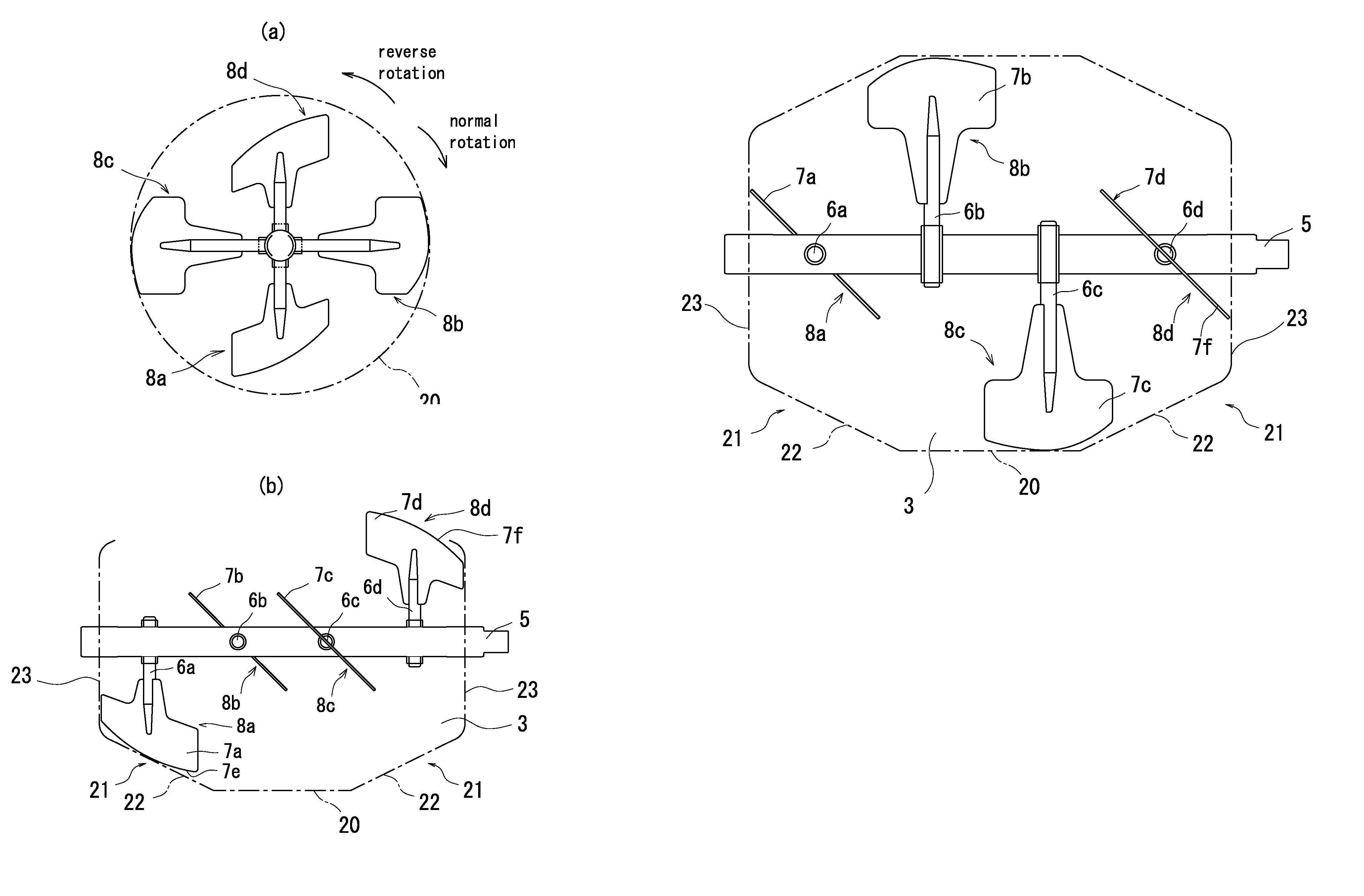
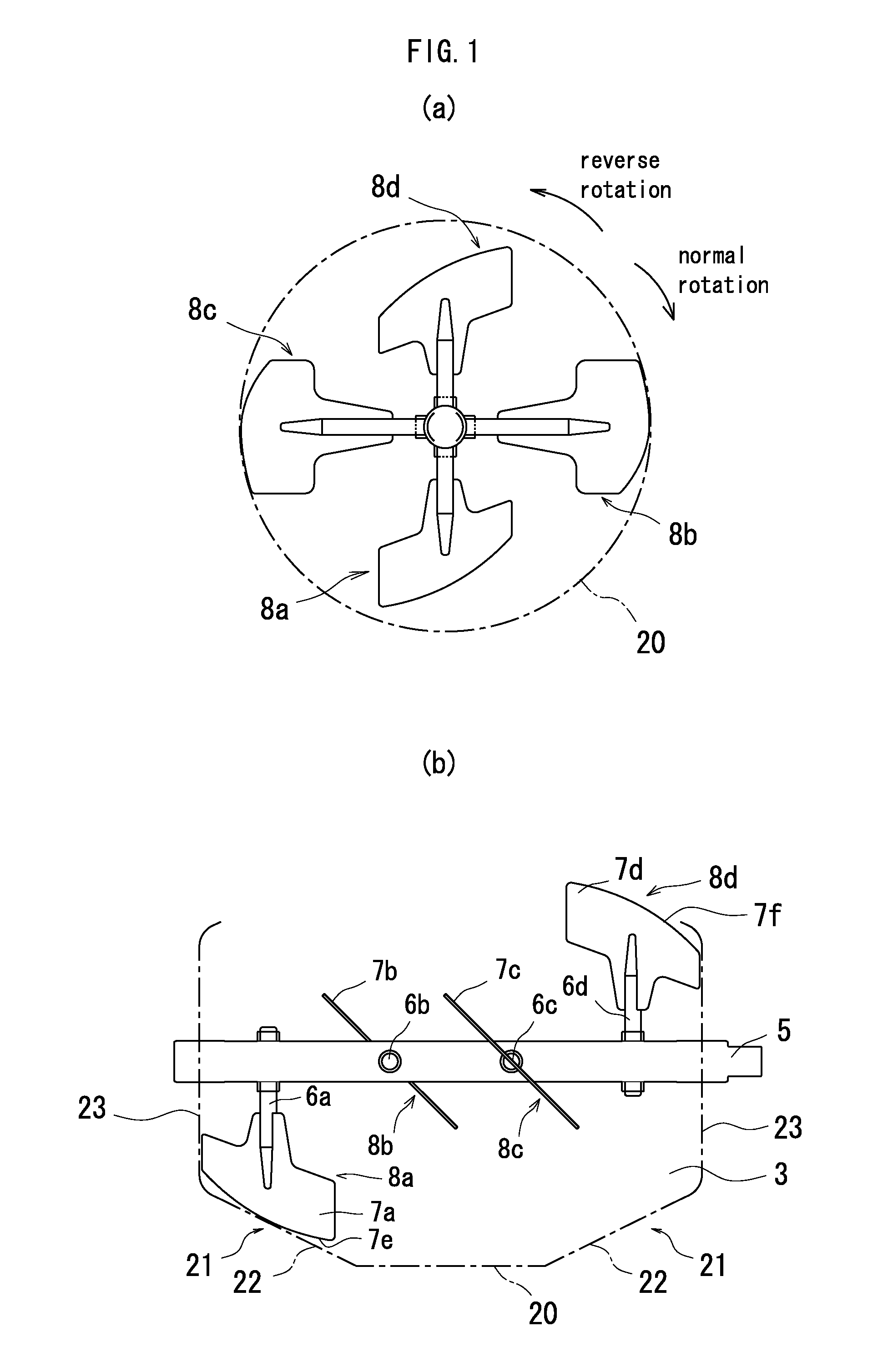
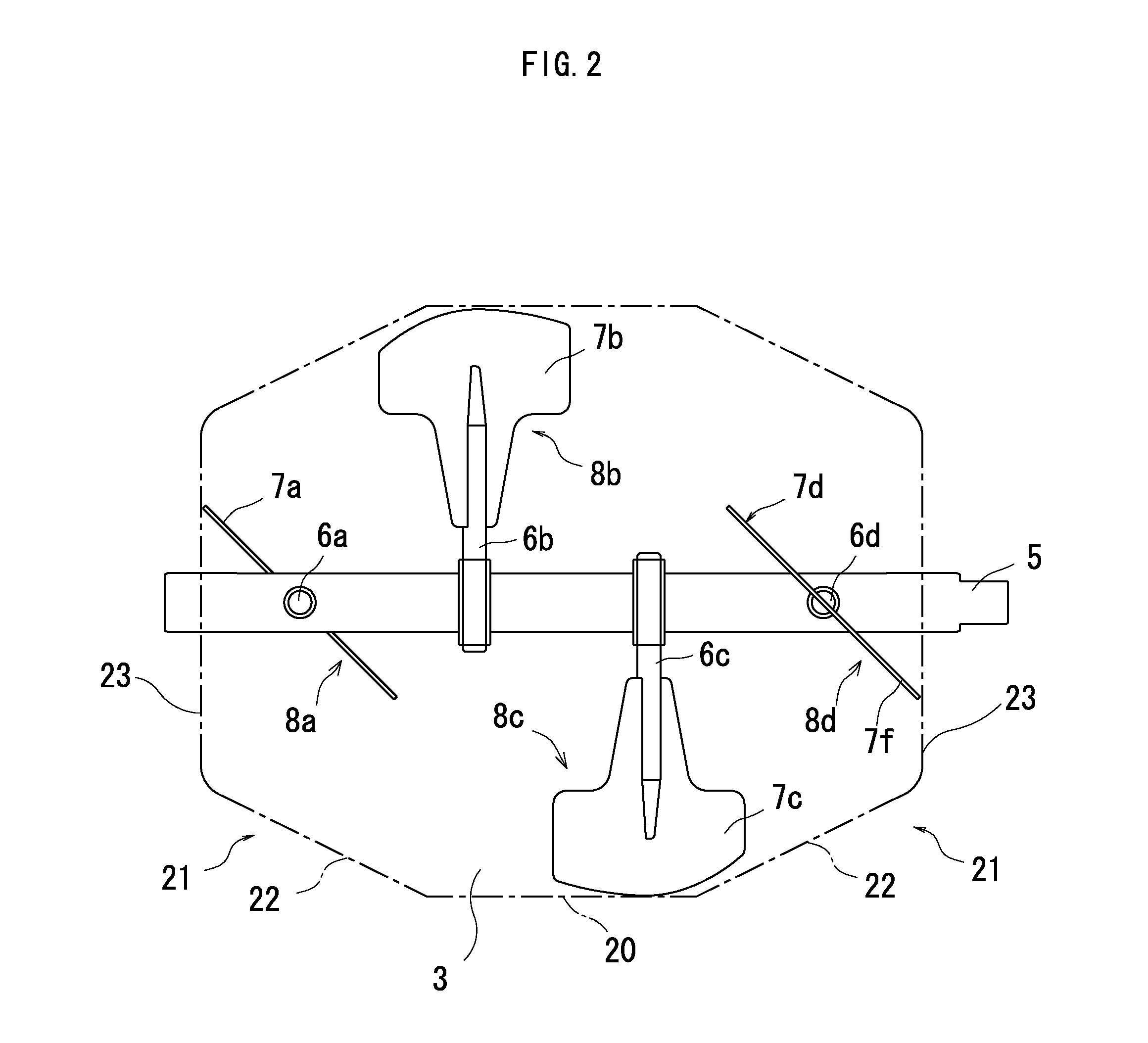
[0031]A particulate mixer 1 is described below in detail as one embodiment of the invention with reference to the accompanied drawings of FIGS. 1 through 9. The particulate mixer 1 has a blender 4 that includes a cylindrical drum 2 and a particulate mixing chamber 3, a rotating shaft 5 that is arranged in a horizontal direction in the particulate mixing chamber 3 and is supported on the blender 4 in a rotatable manner, four arms 6a through 6d that are protruded in the radial direction of the rotating shaft 5, and 1st paddle 8a through 4th paddle 8d that have stirring blades 7a through 7d respectively set on the arms 6a through 6d. The four paddles, that is, the 1st paddle 8a through the 4th paddle 8d, are arranged in an axial direction X of the rotating shaft 5. The drum 2 has a cylindrical center portion 20 and side portions 21 connecting with both ends of the center portion 20. Each of the side portions 21 has a lower face 22 and a vertical face 23. The drum 2 is formed in a trunc...


PUM

PropertyMeasurementUnit
angleaaaaaaaaaa
angleaaaaaaaaaa
angleaaaaaaaaaa

Abstract

The particulate mixer is part of a blender that includes a cylindrical drum with a particulate mixing chamber. A rotating shaft is arranged in a horizontal direction in the particulate mixing chamber. Four arms project in a radial direction from the rotating shaft and include four paddles with respective stirring blades spaced from each other in an axial direction on the rotating shaft. The drum has a cylindrical center portion and side portions that communicate with the cylindrical center portion. Each of the side portions has a lower face and a vertical face. The drum is in the form of a truncated cone with the rotating shaft as its axis. The stirring blades have a driving end face and a driven end face with slopes corresponding to the slopes of the lower face of the side portions.

Description

CROSS-REFERENCE TO RELATED APPLICATIONS[0001]This application claims priority to Japanese Patent Application No. 2006-352077 filed Dec. 27, 2006, the contents of which are incorporated herein by reference.[0002]1. Technical Field[0003]The present invention relates to a particulate mixer, and more specifically to a particulate mixer using paddles to mix and blend the particulate.[0004]2. Background Art[0005]The applicant of the present invention has proposed the single paddle structure and the double paddle structure of a particulate mixer as disclosed in Patent Documents 1 and 2. As written in these cited Patent Documents 1 and 2, the particulate mixer has a cylindrical drum and plural paddles arranged along the axial direction of a rotating shaft. Each of the plural paddles has a paddle arm extended in the radial direction of the rotating shaft and a stirring blade attached to the paddle arm. In the double paddle structure, a stirring blade located inside of the paddle arm in the r...

Claims


Application Information

Patent Timeline
Patent Type & Authority Patents(United States)
IPC IPC(8): B01F7/04
CPCA21C1/06B01F3/18B01F7/00133B01F7/00158B01F7/00208B01F7/04B01F15/00824B01F15/027B01F23/60B01F27/0723B01F27/0726B01F27/091B01F27/70B01F35/50B01F35/752B01F27/60
Inventor KATO, FUMIO
Owner TSUKASA
Why Eureka
Try Eureka