Optical and electrical compound connector

a technology of optical compound connectors and connectors, applied in the direction of optical elements, coupling device connections, instruments, etc., can solve the problems of troublesome connection work between the connector and the optical fiber, and achieve the effect of simplifying the connection work

Inactive Publication Date: 2008-12-02
MATSUSHITA ELECTRIC WORKS LTD
View PDF6 Cites 15 Cited by
  • Summary
  • Abstract
  • Description
  • Claims
  • Application Information

AI Technical Summary

Benefits of technology

[0005]The present invention solves the above mentioned problem, and is purposed to provide a compact optical and electrical compound connector which enables to transmit and receive a plurality of systems of light signals and electric signals, concurrently to transmit and receive these signals to and from another electric printed board, and to facilitate the connection work.
[0013]According to such a constitution, since the sheet-shaped base board is used for a signal transmission medium, the light guides and the conductor patterns for a plurality of systems can be formed on a single sheet-shaped base board easily. Furthermore, since the transmission paths of a plurality of systems can be connected in lump with connecting a single sheet-shaped base board to the connector main body, an optical and electrical compound connector, which enables to simplify the connection work, can be realized. Still furthermore, since the transmission and reception of the light signals and the electric signals are performed in the thickness direction of the sheet-shaped base board or from front side in the insertion direction of the sheet-shaped base board, a constitution of electric contact and a constitution of optical coupling unit are simplified in comparison with the case that rod-shaped or wire-shaped conductive wires and optical fibers are connected, and thereby, a compact optical and electrical compound connector can be obtained.

Problems solved by technology

Thus, there is a problem that a work for connecting the connector with the optical fibers is troublesome.

Method used


Image

  • Optical and electrical compound connector
  • Optical and electrical compound connector
  • Optical and electrical compound connector

Examples


first embodiment

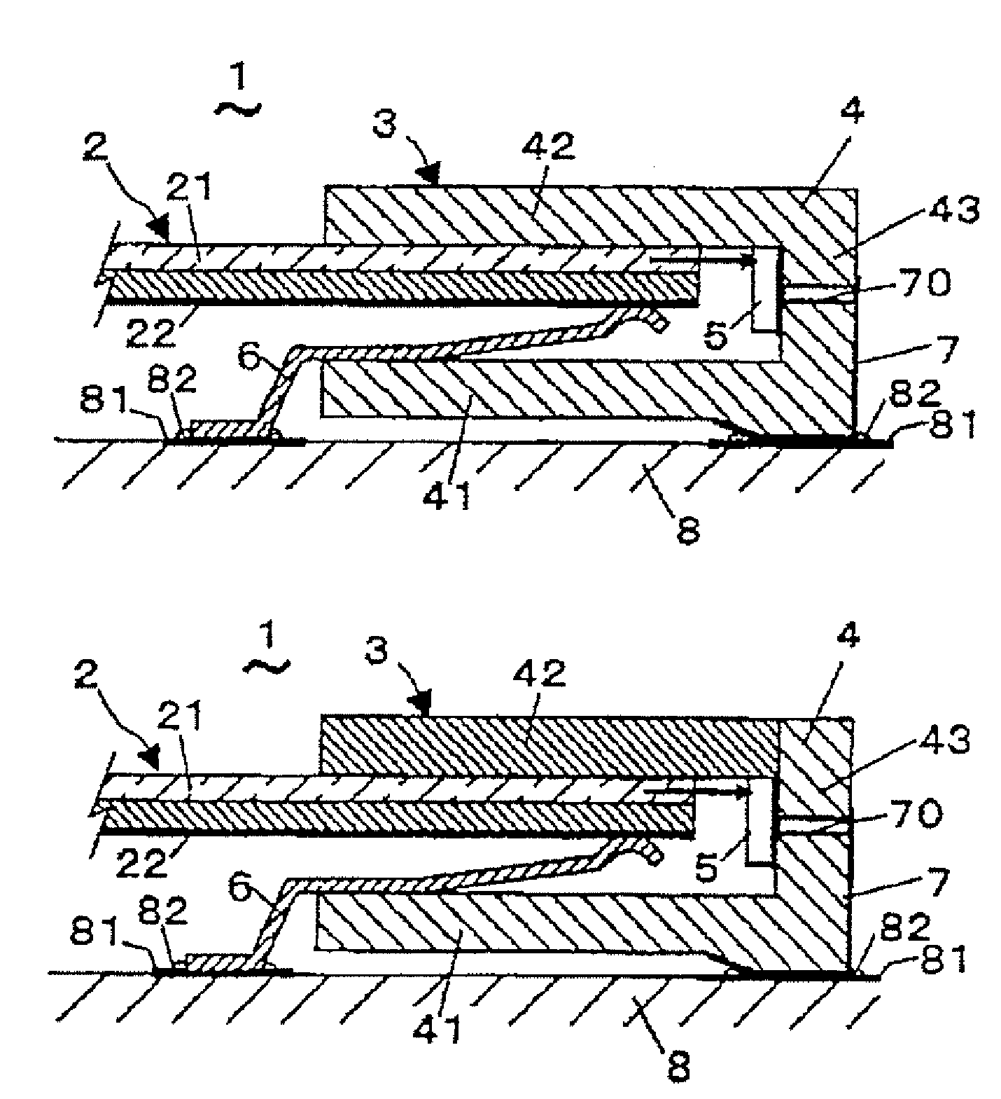
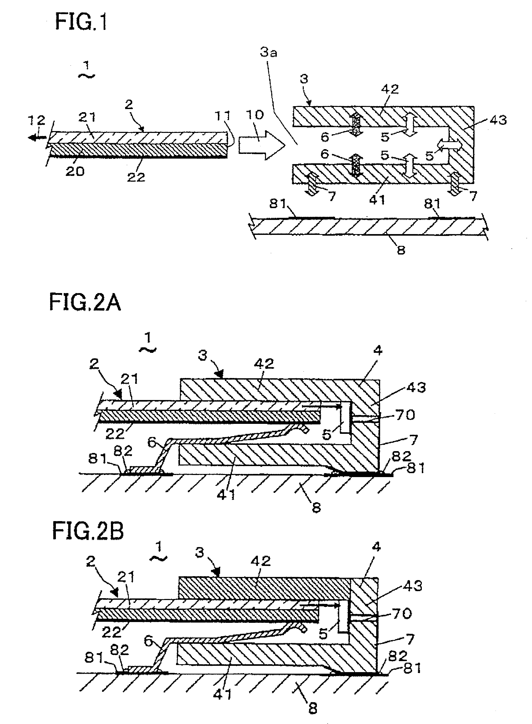
[0046]Subsequently, a specific configuration of the optical and electrical compound connector 1 in accordance with a first embodiment of the present invention is shown FIG. 2A. As shown in FIG. 2A, in the optical and electrical compound connector 1 in accordance with the first embodiment, the light-sensitive element and / or the light emitting element 5 are / is disposed on a front face of the third wall 43 of the body 4 of the socket 3, and the contacts 6 are provided on the first wall 41 side. The sheet-shaped base board 2 is inserted so that the conductor patterns 22 face the first wall 41 side. The conductor patterns 22 and the contacts 6 are electrically connected under a pressurized condition, and the contacts 6 and the wiring patterns 81 of the electric wiring board 8 are electrically connected with solders 82.

[0047]The light guides 21 of the sheet-shaped base board 2 are optically coupled with the light-sensitive element and / or the light emitting element 5 so that end faces of t...

second embodiment

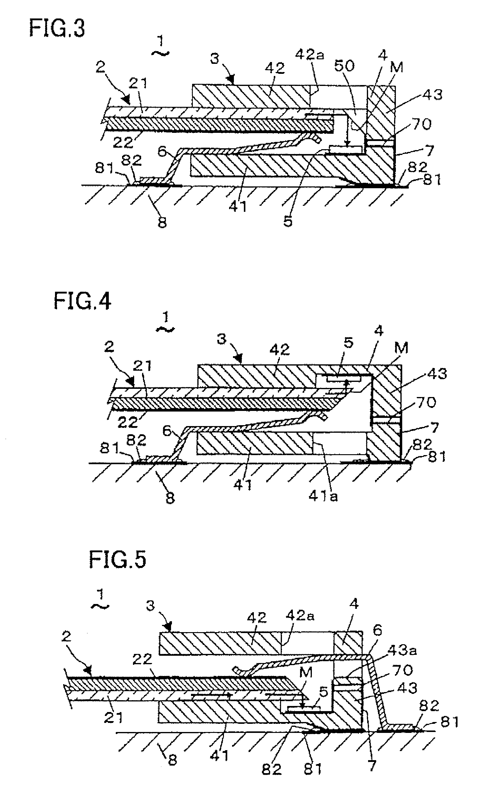
[0050]Subsequently, a specific constitution of an optical and electrical compound connector 1 in accordance with a second embodiment of the present invention is shown in FIG. 3. As shown in FIG. 3, in the optical and electrical compound connector 1 in accordance with the second embodiment, the light-sensitive element and / or the light emitting element 5 are / is disposed on the first wall of the body 4, and a reflection face M is provided at a corner between the second wall 42 and the third wall 43 on which the light-sensitive element and / or the light emitting element 5 are / is not disposed. As for the reflection face M, for example, a slanted face of a prism 50 can be used. In addition, an aperture 42, which is used for an operation of implementation of the light-sensitive element and / or the light emitting element 5, is formed on the second wall 42 of the body 4. Other constitutions are similar to those in case of the above first embodiment.

[0051]According to the optical and electrical...

third embodiment

[0052]Subsequently, a specific constitution of an optical and electrical compound connector 1 in accordance with a third embodiment of the present invention is shown in FIG. 4. As shown in FIG. 4, in the optical and electrical compound connector 1 in accordance with the third embodiment, the end face of the light guide 21 in the insertion direction 10 of the sheet-shaped base board 2 is polished to be slanted, for example, 45 degrees, and the end face of the light guide 21 is used as the reflection face M with no processing or with evaporation of reflection film on the end face of the light guide 21. The light-sensitive element and / or the light emitting element 5 are / is disposed in a recess formed on the second wall 42 of the body 4. In addition, an aperture 41a, which is used for an operation of implementation of the light-sensitive element and / or the light emitting element 5, is formed on the first wall 41 of the body 4.

[0053]According to the optical and electrical compound connec...


PUM


Abstract

An optical and electrical compound connector, which enables to transmit and to receive light signals and electric signals of a plurality of systems and to transmit and to receive these signals with respect to other electric wiring board, is achieved with downsizing and easing connection work thereof. The optical and electrical compound connector 1 is comprised of a sheet-shaped base board 2 and a socket 3 into which this base board 2 is inserted. The sheet-shaped base board 2 is a flexible base board capable of transmission and reception of the light and electric signals, in which a light guide 21 and conductor patterns 22 extended in an insertion direction 10, are formed. The socket 3 performs the transmission and reception of the light and electric signals with the sheet-shaped base board 2 and transmits and receives the signals with an electric wiring board 8. The socket 3 comprises a connector main body 4 to which the sheet-shaped base board 2 is connected, a light-sensitive element and / or a light emitting element 5 which performs the transmission and / or reception of the light signals with the light guide 21, and contacts 6 which performs the transmission and / or reception of the electric signals with the conductor patterns 22. The connector main body 4 has a first to third walls 41 to 43 enclosing the sheet-shaped base board 2 from both sides in a thickness direction and from a front end 11 side, and the light-sensitive element and / or the light emitting element 5 and the contacts 6 are disposed on any one of these walls.

Description

TECHNICAL FIELD[0001]The present invention relates to an optical and electrical compound connector which can transmit light signals and electric signals simultaneously.BACKGROUND ART[0002]In signal transmission, light signals are conventionally used for purposes of speeding up of communication, improvement of anti-noise performance and light-weighting of communication equipment. For transmitting and receiving of the light signals, optical connectors to connect optical transmission paths are used. When connecting such optical transmission paths, it may be demanded to connect electric wires simultaneously. For example, with respect to electric wiring for power supply, it is sufficient only to transmit and receive light signals without connecting electric wirings in communication between devices each having an electric power supply individually. However, in case of supplying electric power to a device or an element having no electric power supply, it is necessary ensure electric wiring...

Claims


Application Information

Patent Timeline
Patent Type & Authority Patents(United States)
IPC IPC(8): G02B6/36G02B6/12
CPCG02B6/3817G02B6/42G02B6/4292H01R12/79G02B6/4214G02B6/4249H01R12/716H01R12/721G02B6/36H01R12/77H01R13/46
Inventor HARANO, TOMOKAZUIIDA, MITSURUHASHIMOTO, SHINJI
Owner MATSUSHITA ELECTRIC WORKS LTD
Why Eureka
Try Eureka