Leisure vehicle

a technology for vehicles and sports, applied in the field of sports vehicles, can solve the problems of increased engine braking, difficulty in achieving desired deceleration or engine braking,

Active Publication Date: 2008-12-02
KAWASAKI MOTORS LTD
View PDF2 Cites 11 Cited by
  • Summary
  • Abstract
  • Description
  • Claims
  • Application Information

AI Technical Summary

Benefits of technology

[0009]In accordance with the leisure vehicle constructed above, when the rider performs the throttle close operation to close the throttle valve, in order to, for example, decelerate a vehicle speed, the engine braking acts as follows. The throttle close operation sensor unit detects that the rider has performed the throttle close operation in order to effect the engine braking, and the slip sensor unit detects a slip state of the drive wheel. In response to this, the controller causes the throttle valve position changing device of the throttle device to operate to increase the engine speed. Thus, a braking force of the engine brake in a low engine speed range is made smaller than that obtained without the control. As a result, it is possible to generate engine braking that is less likely to cause the rear wheel to slip.
[0018]The leisure vehicle may further comprise a gear change sensor unit configured to detect a gear position change of a transmission. The controller may be configured to, for a moment, cause the idle stopper operation device to operate to change the position of the idle stopper to open the throttle valve to a predetermined state, when the gear change sensor unit detects shift down performed by the rider. With such a configuration, a downshift to select a lower gear position can be smoothly performed.
[0021]In accordance with the leisure vehicle constructed above, when the rider performs a throttle open operation to open the throttle valve to the predetermined degree or more, the controller causes the throttle valve position changing device to operate to change the closed position of the throttle valve from the idling position corresponding to the idling engine speed to the open position. Under this condition, when the rider performs a throttle close operation to close the throttle valve to, for example, decelerate a vehicle speed, the throttle valve position changing device operates to inhibit the throttle valve from being closed to the open position or less. Thus, a braking force of the engine brake that is smaller than that obtained without the control is obtained. As a result, it is possible to generate engine braking that is less likely to cause the rear wheel to slip.
[0026]In accordance with the leisure vehicle constructed above, when the rider performs the operation to close the throttle in order to decelerate a vehicle speed, the dash pot applies the pressing force to the throttle valve being closed according to the close operation when the throttle valve moves into the predetermined range, to thereafter cause the throttle valve to be closed at a lower speed. Thus, a braking force of the engine brake that is smaller than that obtained without the control is obtained in a low engine speed range. As a result, it is possible to generate engine braking that is less likely to cause the rear wheel to slip.

Problems solved by technology

When a higher gear position is selected instead of an optimal gear position to effect the engine braking, desired deceleration or engine braking may be difficult to achieve, while when a lower gear position is selected, greater engine braking tends to occur.

Method used


Image

  • Leisure vehicle
  • Leisure vehicle
  • Leisure vehicle

Examples


embodiment 1

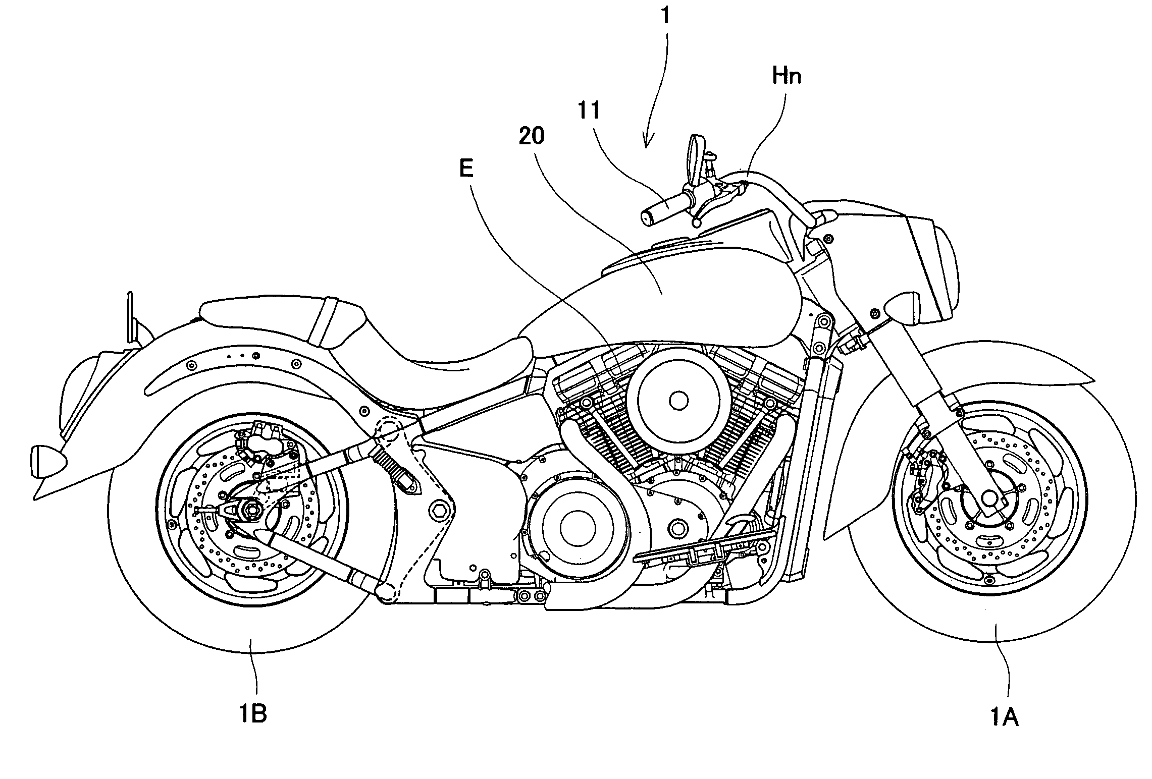
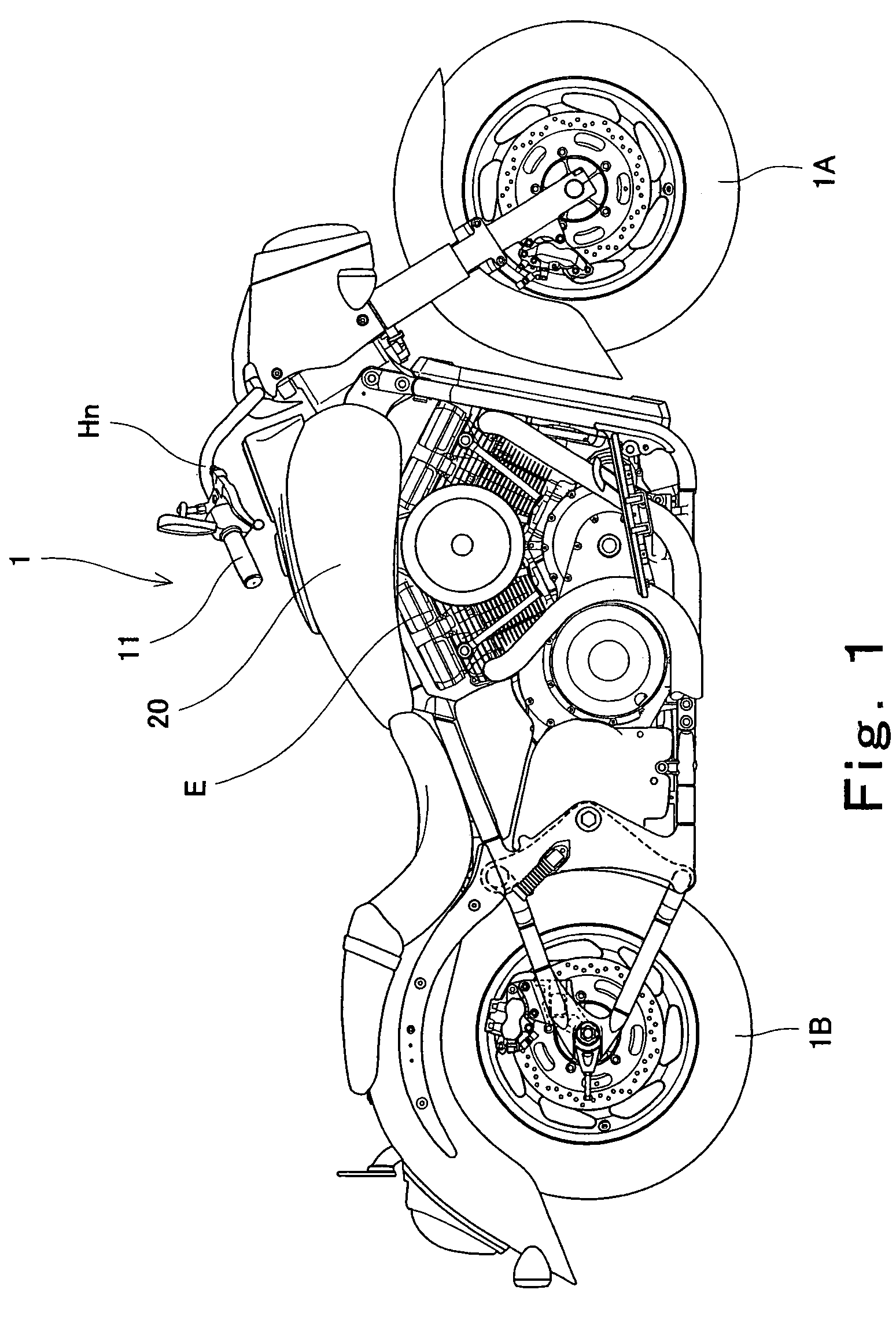
[0045]Turning to FIG. 1, a front wheel 1A of a motorcycle 1 is a non-drive (free) wheel. A front wheel speed sensor unit 2A (see FIG. 2) is attached to the front wheel 1A and is configured to detect a rotational speed of the front wheel 1A. As a power unit to drive the motorcycle 1, a four-cycle internal combustion engine E is disposed below a fuel tank 20. A rear wheel 1B of the motorcycle 1 is a drive wheel configured to be driven by the four-cycle engine E. A rear wheel speed sensor unit 2B (see FIG. 2) is attached to the rear wheel 1B and is configured to detect a rotational speed of the rear wheel 1B.

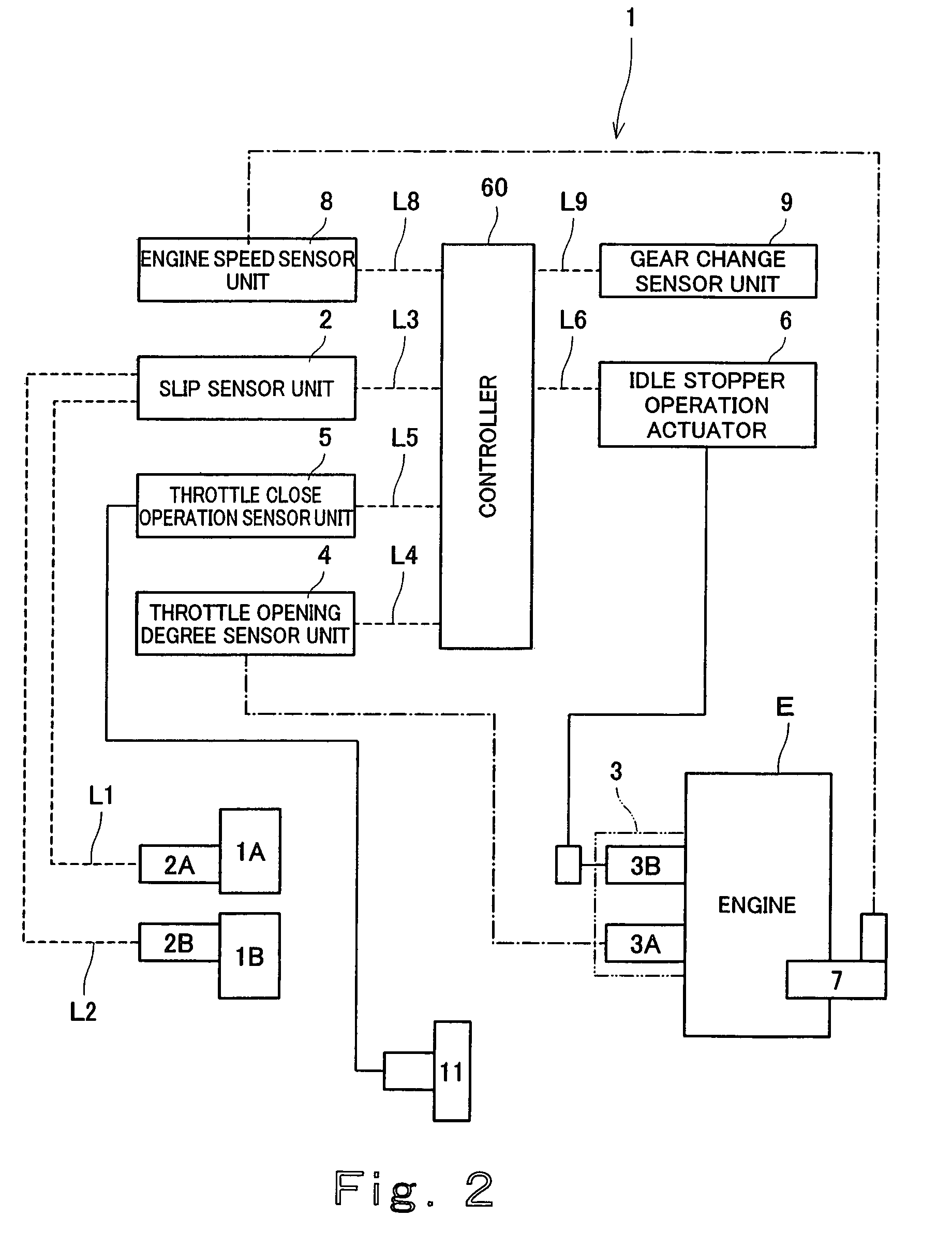
[0046]As shown in FIG. 2, the front wheel speed sensor unit 2A and the rear wheel speed sensor unit 2B are coupled to a slip sensor unit 2 in a control unit through signals lines L1 and L2, respectively. The slip sensor unit 2 is configured to detect a slip state of the rear wheel 1B based on a ratio of the rotational speed of the front wheel 1A to the rotational speed of the rear ...

embodiment 2

[0084]Instead of or in addition to the configuration of Embodiment 1, a gear change sensor unit 9 (FIG. 2) is attached in an interior of a transmission (not shown) and is configured to detect a gear position change of the transmission. The gear change sensor unit 9 is communicatively coupled to the controller 60 through a signal line L9. As shown in FIG. 8, the controller 60 is configured to cause the idle stopper operation actuator 6 to operate for a moment, for example, move up by a predetermined amount (corresponding to approximately 800 rpm in terms of the engine speed) to change the position of the idle stopper 3B to open the throttle valve 3B, thus increasing the engine speed, each time the gear position is shifted down. This enables the downshift to smoothly take place. At an upper part of FIG. 8, a vertical axis indicates an opening degree (Th opening degree) of the throttle valve 3A, a position (Ac position) of the idle stopper 3B, and the engine speed (E / G engine speed), a...

embodiment 3

[0085]As shown in FIGS. 10A and 10B, in order to generate a smaller braking force of the engine brake, a dash pot 230 with a stroke length of St is disposed between a fixed part 203f of a throttle device 203 of the engine E and a pivot shaft 203s of a throttle valve 203A of the throttle device 203 or the throttle valve 203A, to be specific, between the fixed part 203f and an engagement portion 203n attached to the pivot shaft 203s of the throttle valve 203A. The dash pot 230 is configured to be contracted slowly because of an internal fluidic resistance and a spring force applied by a compressive spring (not shown) when the throttle valve 203A is moved to a greatest-degree closed position corresponding to an idling engine speed of the engine by a spring force of a return spring (not shown) mounted on the throttle valve 203A (or a force exerted by the throttle valve operation actuator (not shown)), and is configured to be expanded by the spring force of the compressive spring of the ...


PUM


Abstract

A leisure vehicle equipped with an internal combustion engine as a power unit to drive the leisure vehicle, including a drive wheel, a slip sensor unit configured to detect a slip of the drive wheel, a throttle device mounted to the internal combustion engine, a throttle valve position changing device configured to change a position of a throttle valve of the throttle device, a throttle close operation sensor unit configured to detect that a rider has performed a throttle close operation to close a throttle of the throttle device, and a controller configured to control an operation of the throttle valve position changing device.

Description

TECHNICAL FIELD [0001]The present invention generally relates to a leisure vehicle such as a motorcycle or an all terrain vehicle (ATV) in which, for example, a four-cycle internal combustion engine is mounted as a power unit configured to drive the leisure vehicle. More particularly, the present invention relates to a leisure vehicle configured to optimally control engine braking.BACKGROUND ART [0002]When a rider performs an operation to close a throttle of an engine while traveling in a leisure vehicle, for example, a motorcycle, in which a four-cycle engine is mounted as a power unit to drive the leisure vehicle, a negative drive force (braking torque) is generated in the engine to cause engine braking. As a result, the motorcycle decelerates.[0003]The engine braking is able to assist a brake device to stop the motorcycle smoothly or to decelerate it at a suitable speed near a corner.[0004]In these cases, to enable the engine braking to occur in a suitable condition, the rider se...

Claims


Application Information

Patent Timeline
Patent Type & Authority Patents(United States)
IPC IPC(8): B60W10/04F02D9/02F02D11/10F02D29/02
CPCB60K28/16F02D9/02F02D31/004F02D41/0005F02D41/021B60Y2200/12F02D11/105Y10T477/675F02D2009/0284F02D2009/0294F02D2009/0296F02D2200/0404Y02T10/42Y02T10/40
Inventor MATSUDA, YOSHIMOTO
Owner KAWASAKI MOTORS LTD
Why Eureka
Try Eureka