Triple polarized patch antenna

a patch antenna and triangular technology, applied in the direction of resonant antennas, particular array feeding systems, structural forms of radiating elements, etc., can solve the problems of large arrays that are unsuitable for e.g. hand-held terminals, complex structure of cross-dipoles and loop elements, and difficulty in achieving cross-dipoles and accompanying loop elements at a reasonable cost, etc., to achieve the effect of easy manufacturing

Active Publication Date: 2008-12-02
TELEFON AB LM ERICSSON (PUBL)
View PDF4 Cites 8 Cited by
  • Summary
  • Abstract
  • Description
  • Claims
  • Application Information

AI Technical Summary

Benefits of technology

[0012]A triple polarized antenna made in planar technique is made possible, avoiding space consuming antenna arrangements.
[0013]A triple polarized antenna which is easy to manufacture is obtained.

Problems solved by technology

If more than two orthogonal polarizations are to be utilized for one antenna, it is necessary that it is used in a so-called rich scattering environment having a plurality of independent propagation paths, since it otherwise is not possible to have benefit from more than two orthogonal polarizations.
This, however, results in big arrays that are unsuitable for e.g. hand-held terminals.
It has then been suggested to use three orthogonal dipoles for a MIMO antenna with three ports, but such an antenna is complicated to manufacture and requires a lot of space when used at higher frequencies, such as those used for the MIMO system (about 2 GHz).
Up to six ports have been conceived, as disclosed in the published application US 2002 / 0190908, but the crossed dipole and the accompanying loop element is still a complicated structure that is difficult to accomplish for higher frequencies to a reasonable cost.

Method used


Image

  • Triple polarized patch antenna
  • Triple polarized patch antenna
  • Triple polarized patch antenna

Examples


Embodiment Construction

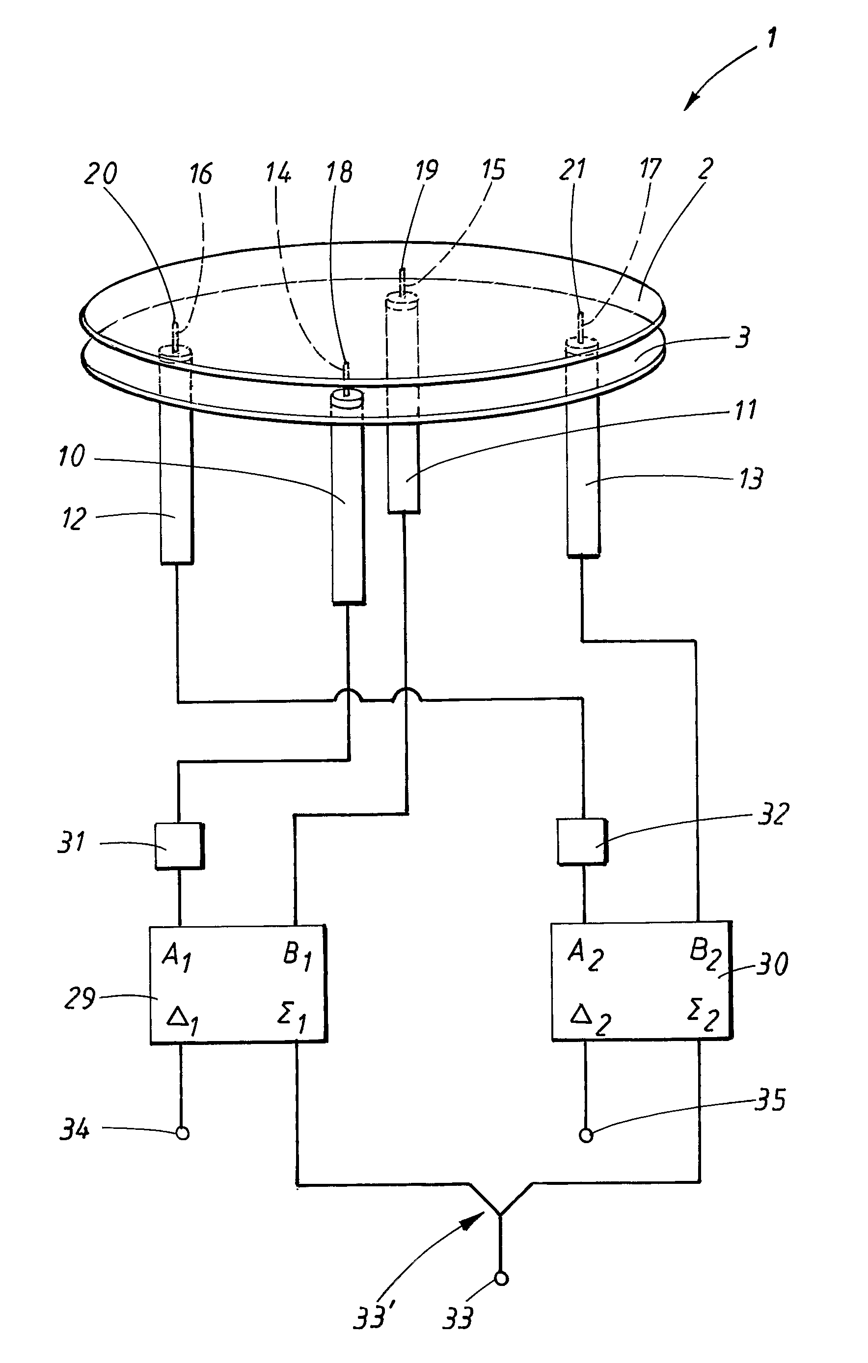
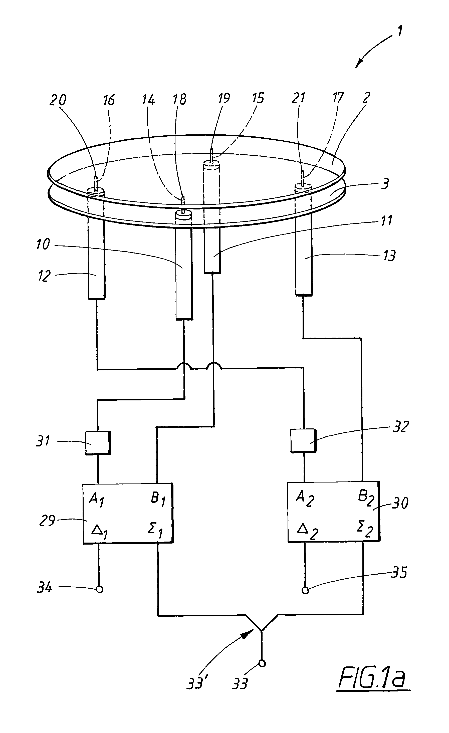
[0021]According to the present invention, a so-called triple-mode antenna arrangement is provided. The triple-mode antenna arrangement is designed for transmitting three essentially orthogonal radiation patterns.

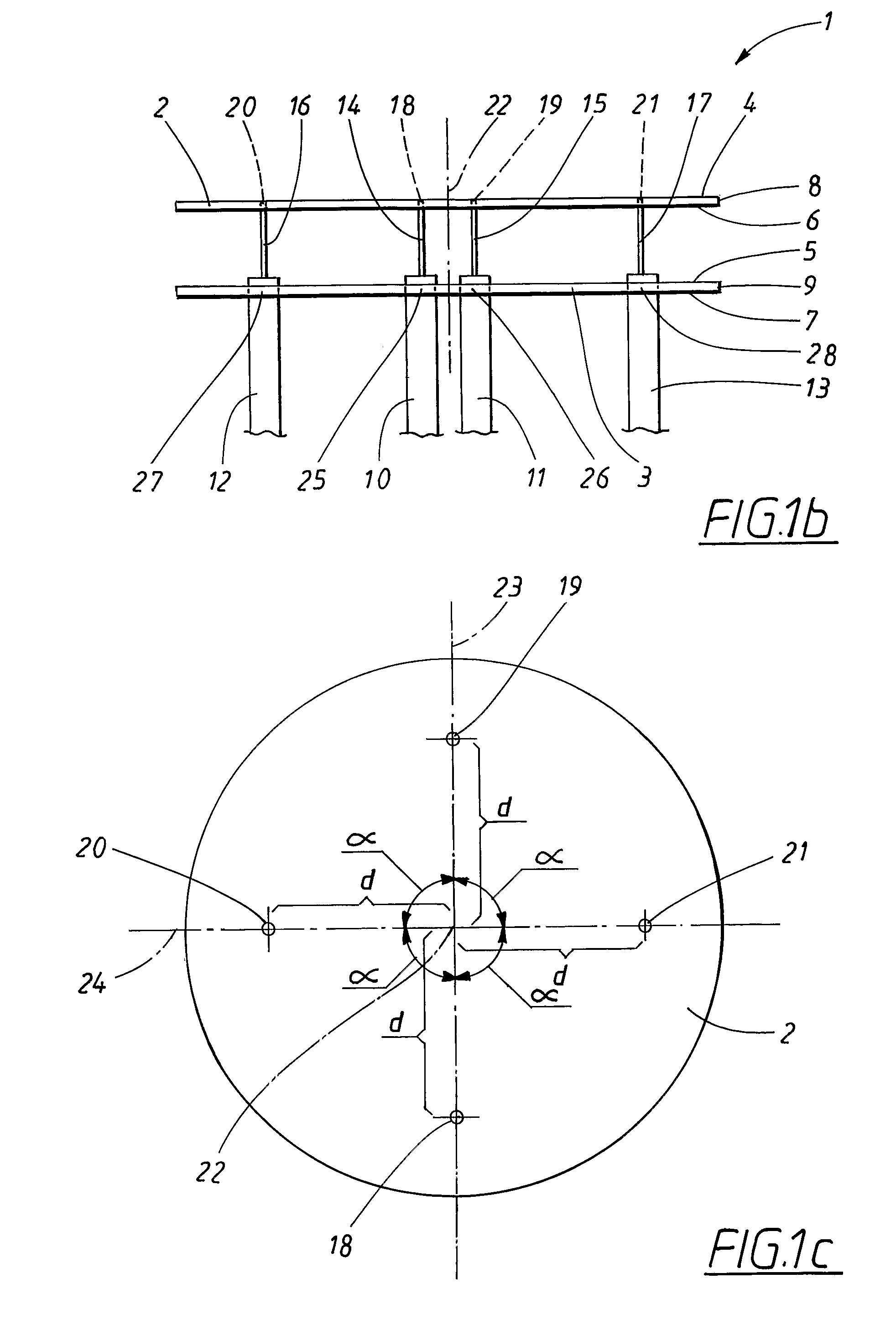
[0022]As shown in FIGS. 1a-b, illustrating a first embodiment of the present invention, a triple-mode antenna arrangement 1 comprises a first 2 and second 3 patch. Each patch 2, 3, is relatively thin, having a centre point, and a first 4, 5 and a second 6, 7 main surface, which first and second main surfaces 4, 5; 6, 7 are essentially parallel to each other. The patches 2, 3 are made in a conducting material, such as copper. The patches 2, 3 are preferably round in shape and placed one above the other with the first patch 2 at the top. The patches 2, 3 also have corresponding first and second edges 8, 9.

[0023]The triple-mode mode antenna arrangement 1 further comprises a first 10, second 11, third 12, and fourth 13 coaxial feed line, having a first 14, second 15, third 16, a...


PUM


Abstract

An antenna arrangement for a Multiple Input Multiple Output (MIMO) radio system, the antenna arrangement transmitting and receiving in three essentially uncorrelated polarizations. The arrangement includes first and second patches, and four feeding points for feeding the first patch. In one mode of operation, the feeding points are fed in phase with each other, resulting in a first constant E-field in a slot between the edges of the patches. In a second operating mode, the first and second feeding points are fed 180 degrees out of phase with each other, resulting in a second E-field in the slot having a first sinusoidal variation. In a third operating mode, the third and fourth feeding points are fed 180 degrees out of phase with each other, resulting in a third E-field in the slot having a second sinusoidal variation uncorrelated with the first sinusoidal variation.

Description

TECHNICAL FIELD[0001]The present invention relates to an antenna arrangement comprising a first and a second patch, each patch being made in a conducting material and having a first and a second main surface, which patches are placed one above the other with the first patch at the top, such that all of said main surfaces are essentially parallel to each other, in which antenna arrangement the first patch has a first edge and the second patch has a second edge, where furthermore the antenna arrangement comprises a feeding arrangement, which feeding arrangement comprises a first, second, third and fourth feeding point, said feeding points being arranged for feeding the second patch, in transmission as well as in reception, each positioned at a distance from a first imagined line passing the patches essentially perpendicular to the respective first and second main surfaces, where a second and third imagined line passes perpendicular to, and intersects, the first line, and where the sec...

Claims


Application Information

Patent Timeline
Patent Type & Authority Patents(United States)
IPC IPC(8): H01Q1/38
CPCH01Q9/0428H01Q3/36H01Q9/0414H01Q21/0012H01Q21/065
Inventor MANHOLM, LARSHARRYSSON, FREDRIK
Owner TELEFON AB LM ERICSSON (PUBL)
Why Eureka
Try Eureka