Method for providing a temporary barrier in a flow pathway

a flow pathway and temporary barrier technology, applied in the direction of functional valve types, sealing/packing, borehole/well accessories, etc., can solve problems such as possible damage to the formation, and achieve the effect of easy removal

Active Publication Date: 2008-12-09
BAKER HUGHES HLDG LLC
View PDF15 Cites 103 Cited by
  • Summary
  • Abstract
  • Description
  • Claims
  • Application Information

AI Technical Summary

Benefits of technology

[0009]Accordingly, it is an object of the present invention to provide a method for temporarily blocking a flow pathway, where the temporary barrier can be easily removed.

Problems solved by technology

Such problems include, but are not necessarily limited to, undesirable leak-off of the working fluid into the formation, and possible damage to the formation.

Method used


Image

  • Method for providing a temporary barrier in a flow pathway
  • Method for providing a temporary barrier in a flow pathway

Examples


Embodiment Construction

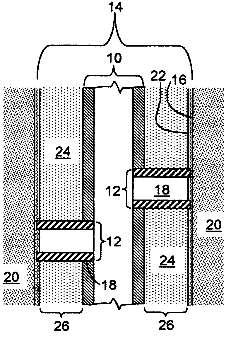
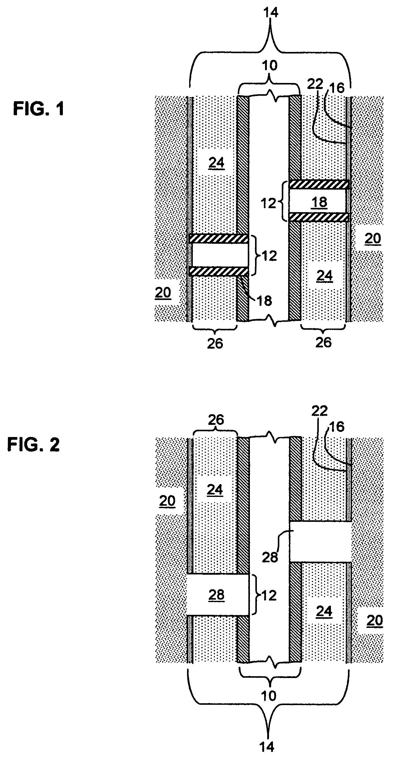
[0016]The present invention utilizes, in one non-limiting embodiment, bio-degradable polymers or other degradable or reactive materials as a temporary barrier and drill-in fluid filter cake breaker for oil well, gas well or injection well completion methods. However, as noted elsewhere herein, the inventive method is not limited to this particular embodiment. In one embodiment of the completion method, a barrier, collar, sleeve, plug or tube, possibly containing a specially sized gravel pack material and run on the casing or liner in place, is placed between a filter cake or other type of coating or membrane on the borehole wall and an orifice in the casing and cemented into place. Once cemented in place, the filter cake needs to be removed for production to occur, or alternatively for injection to take place if the well is an injection well. The production or injection would include fluid flow through the collar, sleeve, plug or tube as well as through the casing or liner. Alternat...


PUM


Abstract

A flow conduit may have at least one orifice is in the vicinity of a flow source. The source is at least partially covered (and flow blocked by) an optional temporary coating or barrier. The flow pathway between the orifice and the source is temporarily blocked with a degradable material or barrier. The material disintegrates (e.g. under the influence of time or temperature) to optionally produce a product that removes the temporary coating in the area adjacent the barrier. The method is useful in one non-limiting context of recovering hydrocarbons where the flow conduit is the casing or liner of the well and the flow source is a subterranean reservoir where the temporary coating is a filter cake.

Description

CROSS-REFERENCE TO RELATED APPLICATION[0001]This application claims the benefit of U.S. provisional patent application No. 60 / 513,425 filed Oct. 22, 2003.FIELD OF THE INVENTION[0002]The present invention relates to methods and compositions for temporarily blocking a flow pathway, and more particularly relates, in one embodiment, to methods and compositions for temporarily blocking a flow pathway to subterranean formations during hydrocarbon recovery operations.BACKGROUND OF THE INVENTION[0003]There are a number of procedures and applications that involve the formation of a temporary seal or plug while other steps or processes are performed, where the seal or plug must be later removed. Often such seals or plugs are provided to temporarily inhibit or block a flow pathway or the movement of fluids or other materials, such as flowable particulates, in a particular direction for a short period of time, when later movement or flow is desirable.[0004]A variety of applications and procedur...

Claims


Application Information

Patent Timeline
Patent Type & Authority Patents(United States)
IPC IPC(8): E21B29/02E21B43/00E21B37/06E21B43/02E21B43/08
CPCE21B37/06E21B43/02E21B43/086Y10T137/1632Y10T137/1804
Inventor RICHARD, BENNETT M.MCELFRESH, PAULWILLIAMS, CHAD
Owner BAKER HUGHES HLDG LLC
Why Eureka
Try Eureka