Acoustic particle alarm including particle sensor

a particle sensor and acoustic particle technology, applied in the field of acoustic particle alarms, can solve the problems of not providing indicators, not providing means to ensure, electrical signals produced by impinging particles are not necessarily provided, etc., to reduce the amount of acoustic coupling, and maximize the concentration of particles impacting the sensor

Inactive Publication Date: 2008-12-09
LINEAR MEASUREMENTS
View PDF6 Cites 7 Cited by
  • Summary
  • Abstract
  • Description
  • Claims
  • Application Information

AI Technical Summary

Benefits of technology

[0016]It is a further object of the invention to provide an acoustic particle alarm comprising a monitoring flow cell including an acoustic sensor that produces an output signal in response to particle impacts in a fluid flow that is impinging on the acoustic sensor, wherein the acoustic sensor is isolated from the flow cell to reduce the acoustic coupling between the acoustic sensor and the other elements of the flow cell.
[0029]Another aspect of the invention involves an acoustic particle alarm comprising a particle sensor that produces an output signal in response to the momentum of particles entrained in a fluid flow impinging on a diaphragm of the sensor, wherein the sensor is disposed within the sensor housing and a nozzle for directing the fluid flow such that a jet of fluid exiting a mouth of the nozzle forms a waist that is located substantially at the diaphragm. The acoustic particle alarm further comprises a mounting block including a detachable sensor housing, wherein a gap is disposed between the sensor housing and the mounting block to reduce the amount of acoustic coupling between the sensor and the mounting block. One or more seals may also be provided between the sensor housing and the mounting block to reduce the amount of acoustic coupling between the sensor and the mounting block.
[0030]According to a preferred implementation of the invention: (1) the nozzle includes a mouth that is disposed at a predetermined distance from the diaphragm; (2) the mouth of the nozzle includes a substantially conical bore that causes the fluid exiting the mouth to form a waist; and (3) the predetermined distance is selected such that the waist is substantially disposed at the diaphragm, thereby maximizing the concentration of particles impacting the sensor. The predetermined distance is selected to be greater than a maximum dimension of the largest particle to be passed. Additionally, a minimum inside diameter of the substantially conical bore is greater than the maximum dimension of the largest particle to be passed. The flow velocity of the fluid through the nozzle is selected to be just below the velocity at which flow noise at the predominant frequency of the sensor impact signals is comparable to the electronic noise in the absence of flow.

Problems solved by technology

One drawback is that means are not provided to ensure that the particles impact the particle sensor in a direction substantially normal to the front face of the sensor rather than following the fluid flow away from the sensor.
A further drawback is that the electrical signal produced by impinging particles is not necessarily a monotonic function of the momentum of the impinging particles.
An additional drawback is that this reference does not provide an indicator for indicating when integrated particle impacts are greater than an acceptable threshold revel.

Method used


Image

  • Acoustic particle alarm including particle sensor
  • Acoustic particle alarm including particle sensor
  • Acoustic particle alarm including particle sensor

Examples


Embodiment Construction

[0037]In the following paragraphs, the present invention will be described in detail by way of example with reference to the attached drawings. Throughout this description, the preferred embodiment and examples shown should be considered as exemplars, rather than as limitations on the present invention. As used herein, the “present invention” refers to any one of the embodiments of the invention described herein, and any equivalents. Furthermore, reference to various feature(s) of the “present invention” throughout this document does not mean that all claimed embodiments or methods must include the referenced feature(s).

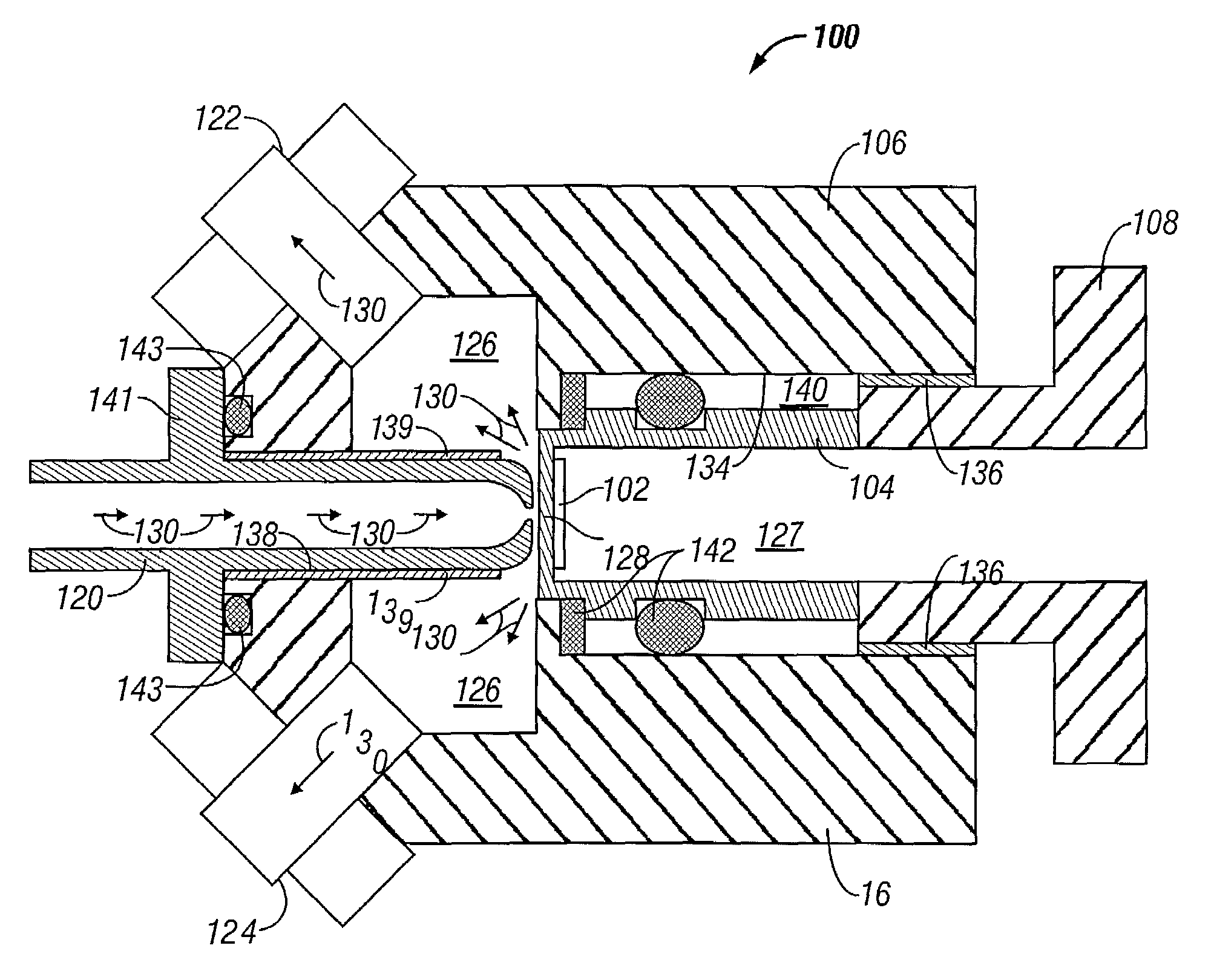
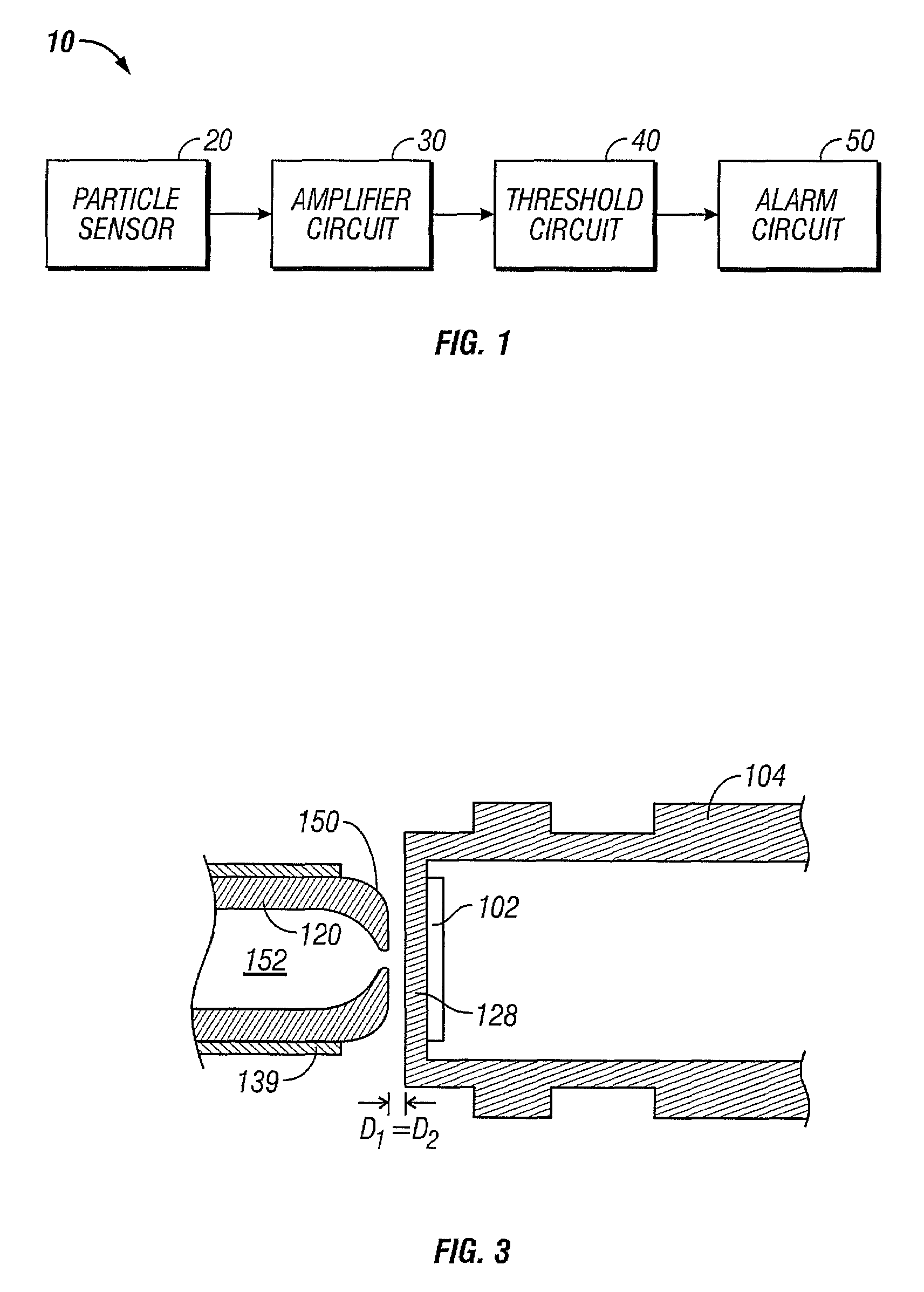
[0038]Particle impacts occur when the motion of a particle-containing fluid is changed by a modification of the flow, such as an obstruction or a bend in a conduit. The resultant particle impacts may be detected due to the transfer of momentum to an acoustic sensor within the conduit. Referring to FIG. 1, the present invention provides an acoustic particle alarm 10 i...


PUM


Abstract

The present invention provides an acoustic particle alarm comprising a particle sensor for indicating the concentration of particles exceeding a specified size and specified concentration, for particles entrained in a fluid flow impinging on a front face of the sensor, and a nozzle for directing the fluid flow such that the particles impact the sensor in a direction substantially normal to the front face of the sensor. Each particle impacting the front face of the sensor causes a response in an output of the sensor with amplitude that is monotonic in the momentum of the impinging particle.

Description

FIELD OF THE INVENTION[0001]The present invention is directed to an acoustic particle alarm, and more particularly, to an acoustic particle alarm including a particle sensor for indicating the concentration of particles exceeding a specified size and concentration entrained in a fluid flow impinging the particle sensor.BACKGROUND OF THE INVENTION[0002]Solid particles entrained in a moving fluid within a conduit can be monitored using acoustic means. Specifically, the sonic and ultrasonic signatures caused when the particles impact the wall of the conduit can be detected due to the transfer of momentum to the surrounding conduit. A sensor such as an acoustic transducer can be inserted either directly into the fluid flow or attached to the surrounding conduit. The fluid can be either a gas such as air or a viscous fluid such and oil or water. Particle impacts occur when the motion of the fluid is changed by a modification of the flow such as a by a bend in the conduit.[0003]U.S. Pat. ...

Claims


Application Information

Patent Timeline
Patent Type & Authority Patents(United States)
IPC IPC(8): G08B21/00
CPCG01N29/02G01N29/222G01N33/28G01N2291/02408G01N2291/02416G01N2291/02809G01N2291/02836
Inventor HATCH, ROBERT K.SQUIRE, WILLIAM D.WHITEHOUSE, HARPER J.
Owner LINEAR MEASUREMENTS
Why Eureka
Try Eureka