Air dynamic steady state and transient detection method for cam phaser movement

a technology of cam phaser and steady state, applied in the direction of valve drives, machines/engines, instruments, etc., can solve the problems of inability to apply the proper air estimation method during inability to detect the transient operating condition or the steady state operating condition of the cam phaser, and inaccurate methods

Active Publication Date: 2008-12-16
GM GLOBAL TECH OPERATIONS LLC
View PDF4 Cites 29 Cited by
  • Summary
  • Abstract
  • Description
  • Claims
  • Application Information

AI Technical Summary

Problems solved by technology

The first method is shown to be inaccurate during movement of cam phasers coupled to intake and exhaust camshafts of the engine.
Conventional methods of estimating air lack the ability to detect a transient operating condition or a steady state operating condition of the cam phasers and lack the ability to apply the proper air estimation method during the transient operating condition.

Method used


Image

  • Air dynamic steady state and transient detection method for cam phaser movement
  • Air dynamic steady state and transient detection method for cam phaser movement
  • Air dynamic steady state and transient detection method for cam phaser movement

Examples


Embodiment Construction

[0014]The following description of the preferred embodiment(s) is merely exemplary in nature and is in no way intended to limit the invention, its application, or uses. For purposes of clarity, the same reference numbers will be used in the drawings to identify the same elements. As used herein, the term module refers to an application specific integrated circuit (ASIC), an electronic circuit, a processor (shared, dedicated, or group) and memory that execute one or more software or firmware programs, a combinational logic circuit, and / or other suitable components that provide the described functionality.

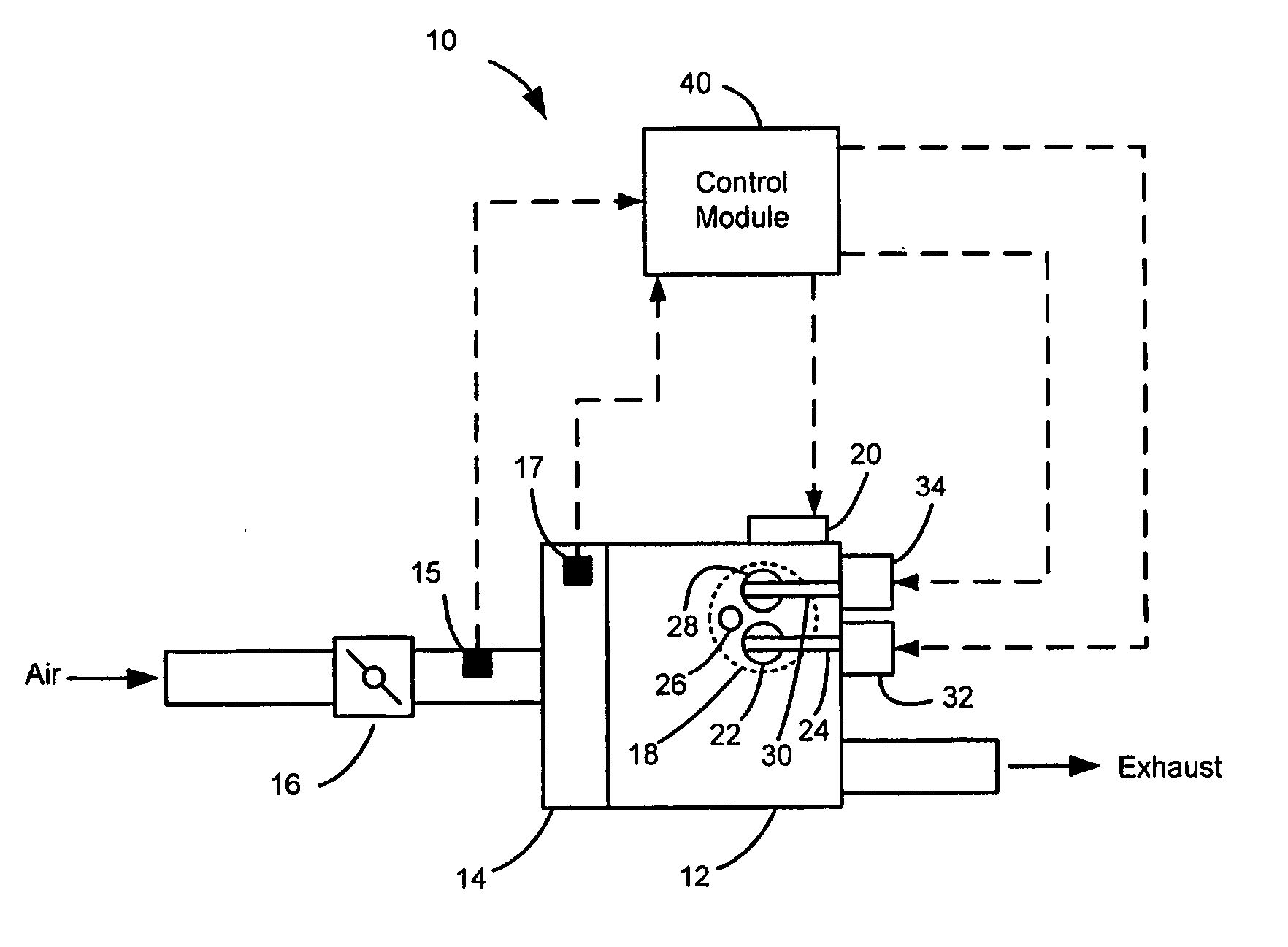
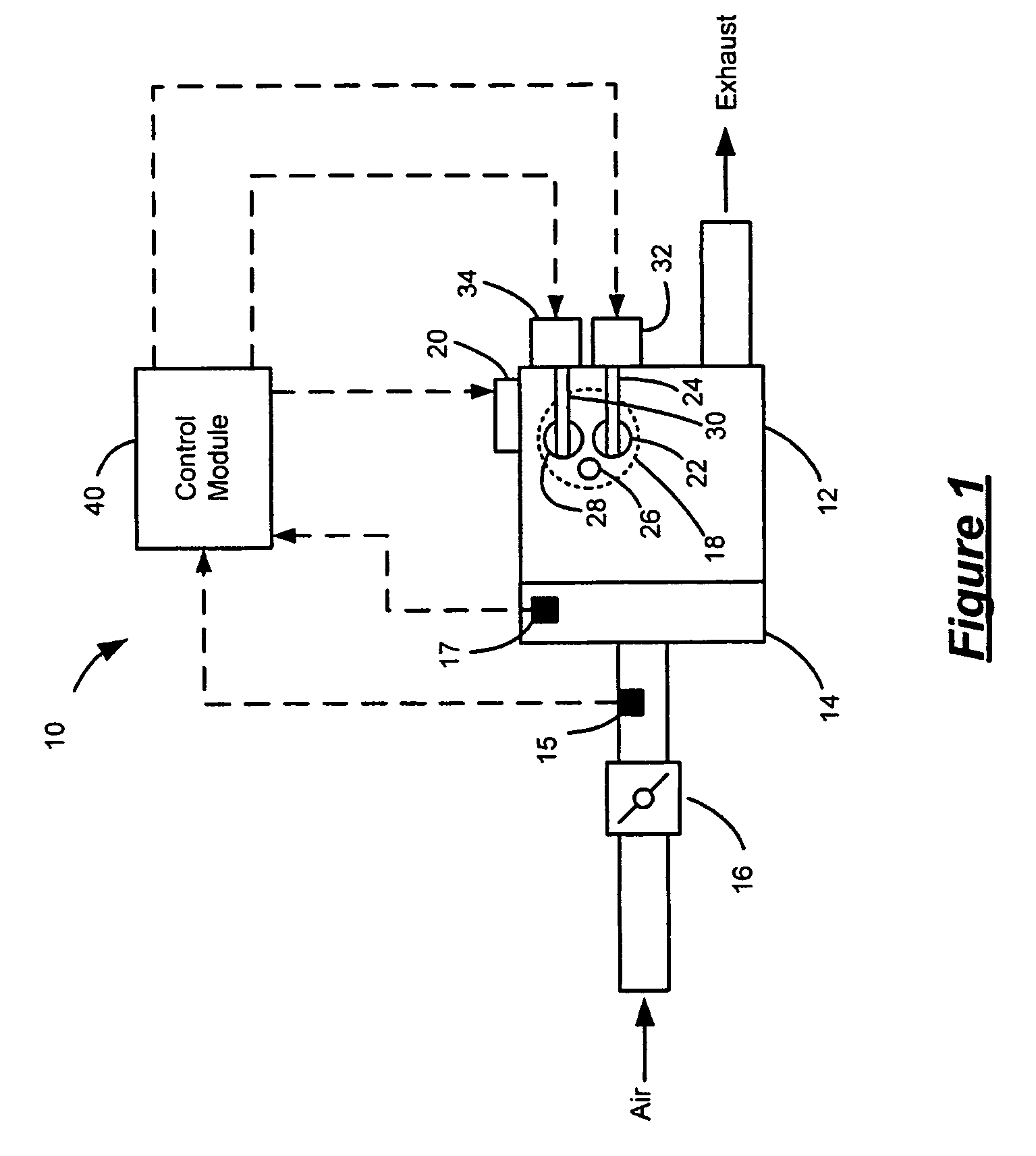
[0015]Referring to FIG. 1, an engine system 10 includes an engine 12 that combusts an air and fuel mixture to produce drive torque. Air is drawn into an intake manifold 14 through a throttle 16. The throttle 16 regulates mass air flow into the intake manifold 14. A mass airflow sensor 15 senses the mass of air flowing into the engine. A manifold absolute pressure sensor 17 senses the...


PUM


Abstract

An air dynamic steady state detection system for movement of a cam phaser of an internal combustion engine includes a cam position sensing device and a control module. The cam position sensing device generates a position signal based on a position of the cam phaser of the engine. The control module receives the position signal and applies first and second filters to the position signal to select either a transient or steady state condition. The control module also calculates an estimated air value based on the selection of the transient or steady state condition.

Description

CROSS-REFERENCE TO RELATED APPLICATIONS[0001]This application claims the benefit of U.S. Provisional Application No. 60 / 702,091, filed on Jul. 22, 2005. The disclosure of the above application is incorporated herein by reference.FIELD OF THE INVENTION[0002]The present invention relates to control systems for internal combustion engines, and more particularly to systems and methods for detecting steady state and transient conditions of a cam phaser that are used for estimating air.BACKGROUND OF THE INVENTION[0003]Various methods exist for estimating the air in an internal combustion engine. One conventional method uses measurements from a mass airflow sensor to estimate an air value. Another conventional method uses speed density calculations to estimate the value.[0004]The first method is shown to be inaccurate during movement of cam phasers coupled to intake and exhaust camshafts of the engine. The second method provides more accurate estimation during transient operating condition...

Claims


Application Information

Patent Timeline
Patent Type & Authority Patents(United States)
IPC IPC(8): F01L1/34
CPCF01L1/344F01L2800/00F01L2820/041
Inventor WIGGINS, LAYNE K.MATTHEWS, GREGORY P.
Owner GM GLOBAL TECH OPERATIONS LLC
Why Eureka
Try Eureka