Low permeability elastic sealing ring

a low-permeability, elastic sealing technology, applied in the direction of sealing, hose connection, cable termination, etc., can solve the problems of poor sealing ability, unsuitable use of 2 elastic rings, and inconvenient fitting

Inactive Publication Date: 2008-12-16
SUMITOMO RIKO CO LTD
View PDF13 Cites 27 Cited by
  • Summary
  • Abstract
  • Description
  • Claims
  • Application Information

AI Technical Summary

Benefits of technology

[0021]The objective of the present invention is a single low permeability elastic sealing ring with a sealing component having the shortest possible length in the axial direction, such that effective use of the space in the piping is realized with minimum fitting time and effort.
[0026]In accordance with the present invention, the multi-layer single elastic ring of the present invention possesses two functions having both low temperature resistant performance and low permeability toward fuel.
[0030]The elastic sealing ring may be tube-shaped in its entirety, for application in a quick connector with (a) a companion pipe inserted into one end thereof in the axial direction and being held by a socket-shaped retainer, and a connector provided with a hose connector component connected to the end of the hose at the other end, and (b) held in a fixed state along the axial direction from the retainer holder component, with the retainer acting to prevent a falling out of the companion pipe locked in the axial direction at the engagement flange component on the outer surface of the companion pipe where it is mounted on the inner surface of the connector body of the quick connector.

Problems solved by technology

However, if the sealing material is impermeable to fuel (for example fluoro rubber or fluororesin) but has poor low-temperature performance, there may be a problem with poor sealing ability due to a loss of elastic strength at low temperatures.
Since the space for piping in vehicles is limited, the use of 2 elastic rings is undesirable in the sense of using the space efficiently.
Moreover, when fitting the elastic sealing rings into connector body 202, a much longer fitting time is required to fit two separate elastic sealing rings 214, 216, and produces a fitting problem.

Method used


Image

  • Low permeability elastic sealing ring
  • Low permeability elastic sealing ring
  • Low permeability elastic sealing ring

Examples


Embodiment Construction

[0039]The following embodiments of the present invention are discussed in detail on the basis of the accompanying figures:

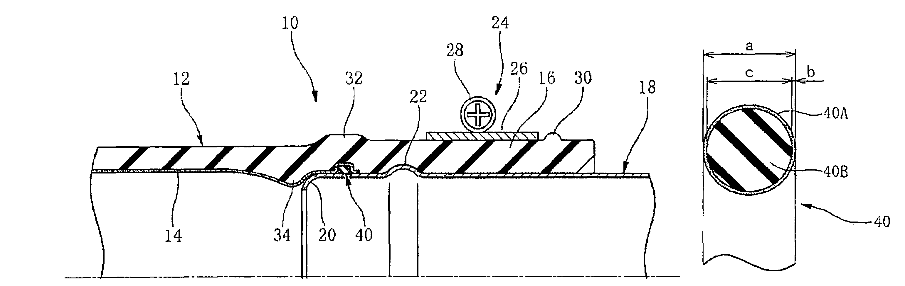
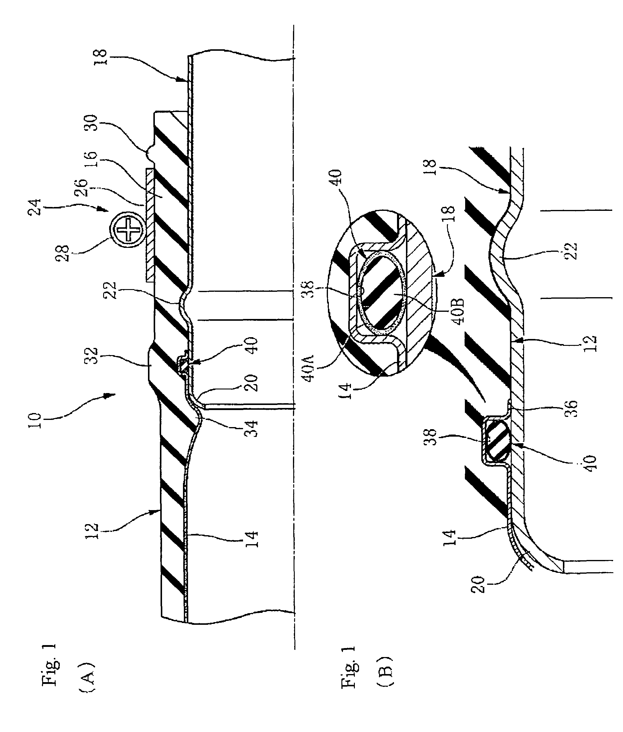
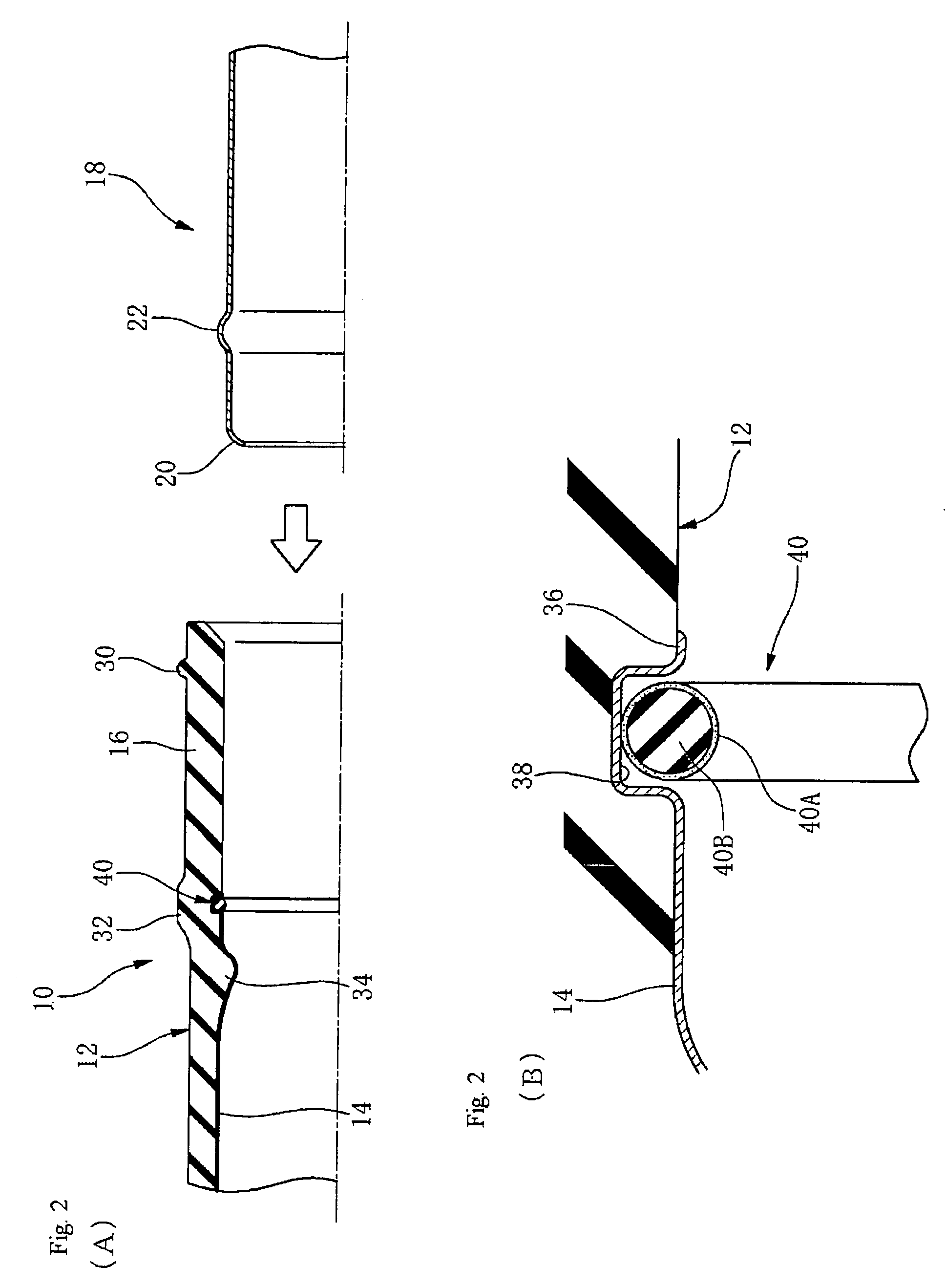
[0040]In FIG. 1, 10 is a fuel supply hose (referred to below simply as hose), 12 is hose body piping formed from an elastic body that forms the main body, and 14 is a laminated layer formed on the inner surface, which is a hard resin layer that functions as a barrier layer possessing impermeability to fuel.

[0041]This resin layer 14 is not laminated over the entire length of the inner surface of hose body piping 12 and instead the end part 16 of the hose 10 is left exposed, so that the inner surface of hose body piping 12 is directly exposed at end part 16.

[0042]A metal companion pipe 18 represents a connection partner of the quick connect assembly and includes a straight tube with a straight shape in the axial direction having an outer diameter of slightly larger diameter than the inner diameter of end part 16.

[0043]This companion pipe 18 has an insertion end wit...


PUM

PropertyMeasurementUnit
temperature-resistanceaaaaaaaaaa
elasticityaaaaaaaaaa
temperatureaaaaaaaaaa

Abstract

A laminated low-permeability elastic ring (40) comprising an outer layer (40A) of a low permeability material that possesses impermeability to automotive fuel, and an inner core part (40B) of a low temperature-resistant material with excellent low temperature performance in order to maintain high elastic strength at low temperatures for the low permeability material layer.

Description

TECHNICAL FIELD[0001]The present invention relates to an elastic sealing ring that forms a seal for use in a fuel supply piping system, and more particularly to a low permeability elastic sealing ring with excellent impermeability to fuel.BACKGROUND ART[0002]In automotive fuel supply pipes, an elastic sealing ring is fitted into the connector that connects one piping component to another piping component, so that this elastic sealing ring prevents the fuel from leaking between one piping component and another piping component.[0003]In recent years, permeation of automotive fuel from the piping system is being regulated more strictly, and it is anticipated that these regulations will become increasingly stringent in the future.[0004]Accordingly, not only must the elastic sealing ring prevent leakage of the fuel from the fuel supply piping, but it must have excellent impermeability to the fuel, i.e., low permeability is required.[0005]An elastic sealing ring is mounted in the connecti...

Claims


Application Information

Patent Timeline
Patent Type & Authority Patents(United States)
IPC IPC(8): F16L17/00F16J15/06F16J15/08F16J15/10
CPCF16J15/064F16J15/104F16L33/18F16L37/0987Y10S277/91
Inventor SAKAZAKI, KAZUSHIGEHIOKI, KOJI
Owner SUMITOMO RIKO CO LTD
Why Eureka
Try Eureka