Electric connector

a technology of electric connectors and connectors, applied in the direction of connection contact material, coupling device connection, electrical apparatus, etc., can solve the problems of inability to obtain sufficient properties of electromagnetic interference (emi) and electrostatic discharge (esd), and the reliability of contact is not guaranteed in the present circumstances, so as to improve the reliability of electric connectors, improve the electrical contact performance of terminal connecting portions cs, and improve the properties of electromagnetic interference (emi)

Inactive Publication Date: 2008-12-16
DAIICHI SEIKO CO LTD
View PDF4 Cites 17 Cited by
  • Summary
  • Abstract
  • Description
  • Claims
  • Application Information

AI Technical Summary

Benefits of technology

[0010]According to the electric connector having such a configuration, since the shell connecting portion SS disposed opposite to the terminal connecting portion CS of the first and second connector functions to maintain contact pressure at the terminal connecting portion CS well, electric contact performance of the terminal connecting portion CS is improved.
[0011]Further, since the shell connecting portion is disposed opposite to the terminal connecting portion CS, a shield wire formed by the conductive shells of both the connectors is formed continuously, and it further becomes possible to dispose the shield wire along an electric signal wire formed by the conductive terminals of both the connectors, so that electromagnetic waves generated by the electric signal wire can be shielded well.
[0012]As described above, according to the electric connector according to the present invention, even if an electric connector is lowered in height and downsized, contact reliability of conductive terminals can be maintained well, and simultaneously improvement of properties of electromagnetic interference (EMI) and electrostatic discharge (ESD) can be achieved, so that reliability of the electric connector can be improved at low cost.

Problems solved by technology

However, also in such a vertically-fitting type electric connector, lowering in height and downsizing have been rapidly promoted as in the case of another electric connector, since space allowing displacement of conductive terminals at a fitting time is reduced so that contact pressure of the conductive terminals is lowered, which may result in a problem in contact reliability which is the most fundamental performance required for an electric connector.
However, in a general electric connector, for example, as disclosed in JP-A-2005-302417, since a conductive shell covering an insulating housing has no arrangement relationship with conductive terminals, sufficient properties of electromagnetic interference (EMI) and electrostatic discharge (ESD) cannot be obtained in the present circumstances.

Method used


Image

  • Electric connector
  • Electric connector
  • Electric connector

Examples


Embodiment Construction

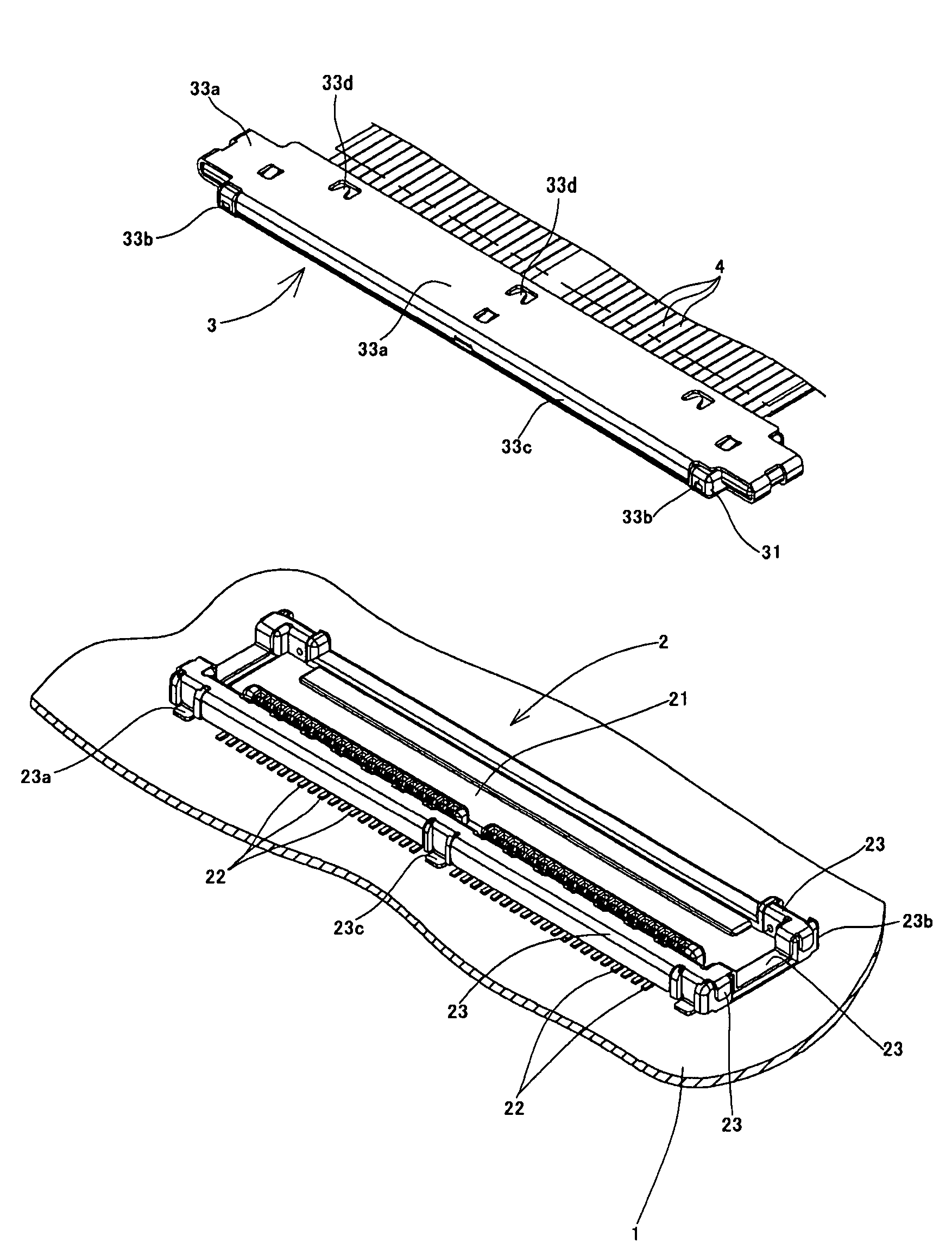
[0023]Hereinafter, an embodiment of the present invention applied to an electric connector which connects a plurality of coaxial cables to a printed circuit board will be explained in detail with reference to the drawings.

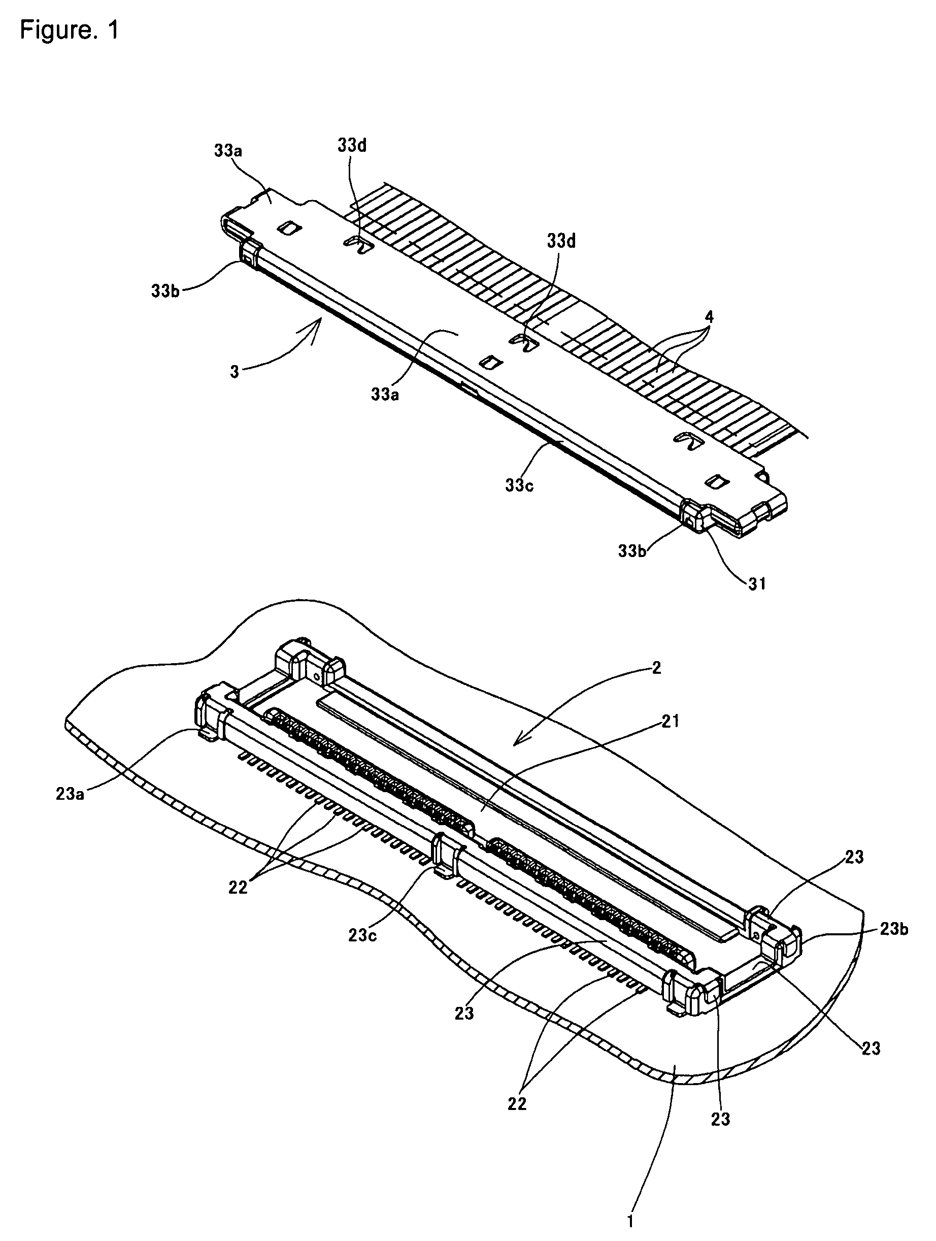
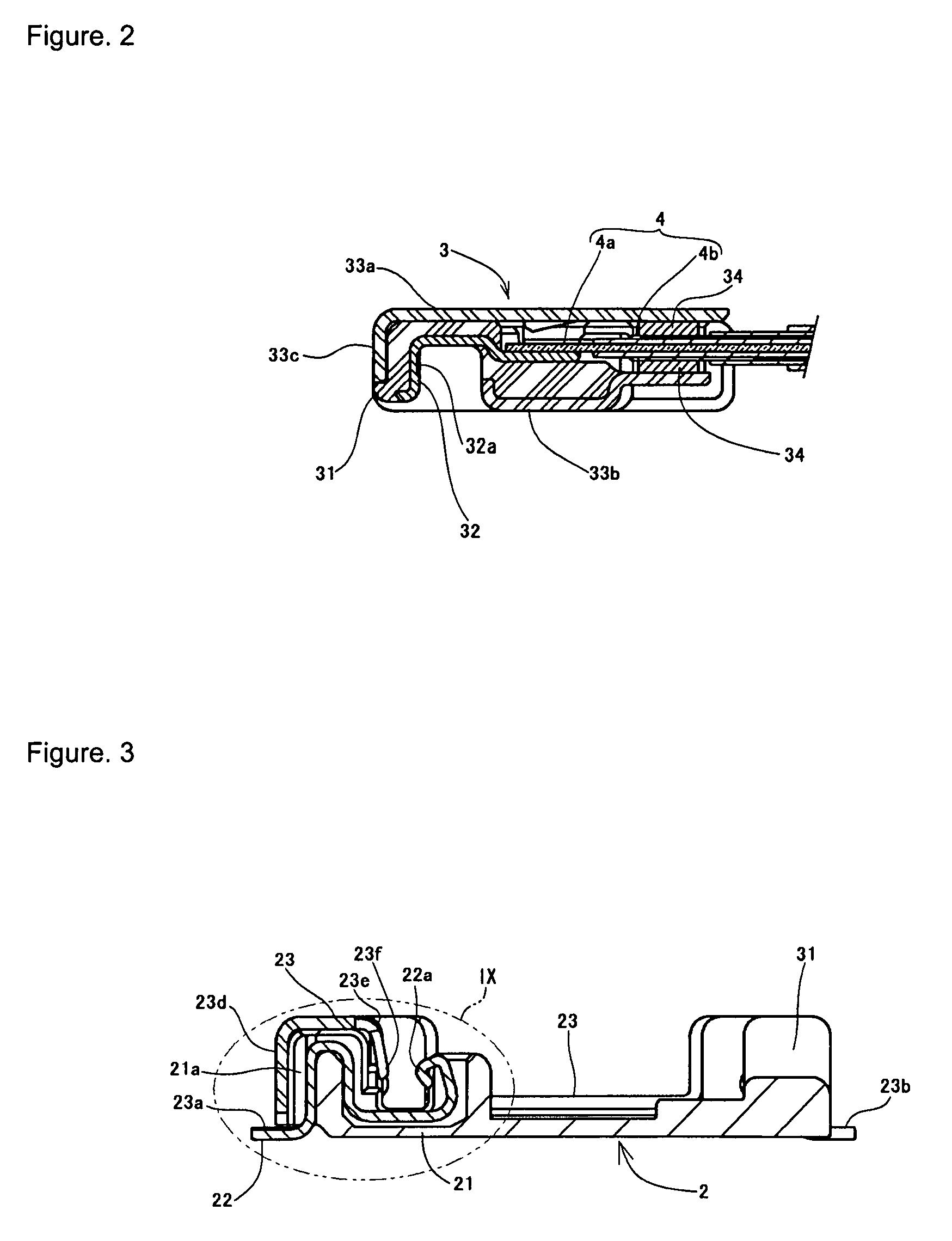
[0024]First, an electric connector shown in FIG. 1 includes a receptacle connector (first connector) 2 mounted on a printed circuit board 1 and a plug connector (second connector) 3 fitted to the receptacle connector 2. That is, an electric connector according to the present invention has a vertically-fitting type configuration in which the plug connector 3 which is disposed just above the receptacle connector 2 is brought down in FIG. 1 in a direction approximately perpendicular to the printed circuit board 1 to plug a fitting portion of the plug connector 3 into a fitting portion of the receptacle connector 2 so that both the connectors are fitted to each other.

[0025]Hereinafter, a direction in which the plug connector 3 is plugged is downward, and an opposite di...


PUM


Abstract

Such a configuration is achieved that shell connecting portion which is a contact portion of conductive shells of first and second connectors fitted to each other in a direction approximately perpendicular to multipolar arrangement is disposed opposite to a terminal connecting portion which is a contact portion of conductive terminals, so that contact pressure at the shell connecting portion is caused to function on the terminal connecting portion to improve electric contact performance of the terminal connecting portion, and the conductive shells are disposed approximately along the conductive terminals to improve a function for shielding electromagnetic waves generated based upon electric signals flowing in the conductive terminals. By adopting such a configuration, even if an electric connector is lowered in height and downsized, contact reliability of the conductive terminals is maintained well, so that improvement of properties of electromagnetic interference (EMI) and electrostatic discharge (ESD) can be achieved.

Description

BACKGROUND OF THE INVENTION[0001]1. Field of the Invention[0002]The present invention relates to an electric connector configured such that first and second connectors are fitted to each other in a direction approximately perpendicular to a multipolar arrangement direction of conductive terminals (contacts).[0003]2. Description of the Related Art[0004]Generally, in various electric apparatuses, it has been widely performed to connect a plurality of coaxial cables, a flexible circuit board, or the like to a printed circuit board via a pair of electric connectors configured to allow fitting connection to each other. As the pair of electric connectors, for example, a receptacle connector (first connector) mounted on a printed circuit board and a plug connector (second connector) fitted to the receptacle connector are used. In a state in which end portions of a plurality of coaxial cables, an end portion of a flexible circuit board, or the like are joined to the plug connector, the plug...

Claims


Application Information

Patent Timeline
Patent Type & Authority Patents(United States)
IPC IPC(8): H01R12/24H01R12/79
CPCH01R12/598H01R13/6592H01R12/592H01R12/716H01R12/79H01R13/6485
Inventor YOTSUTANI, KENICHI
Owner DAIICHI SEIKO CO LTD
Why Eureka
Try Eureka