
Liquid ring pumps with hermetically sealed motor rotors

a technology of motor rotors and liquid ring pumps, which is applied in the direction of liquid fuel engine components, energy recovery in distillation, and coke oven details, etc., can solve the problems of large-scale water systems that require both significant infrastructure and highly trained operators, and the techniques are only well suited to centralized techniques, so as to achieve convenient maintenance

Active Publication Date: 2008-12-16
DEKA PROD LLP
View PDF143 Cites 58 Cited by
  • Summary
  • Abstract
  • Description
  • Claims
  • Application Information

AI Technical Summary

Benefits of technology

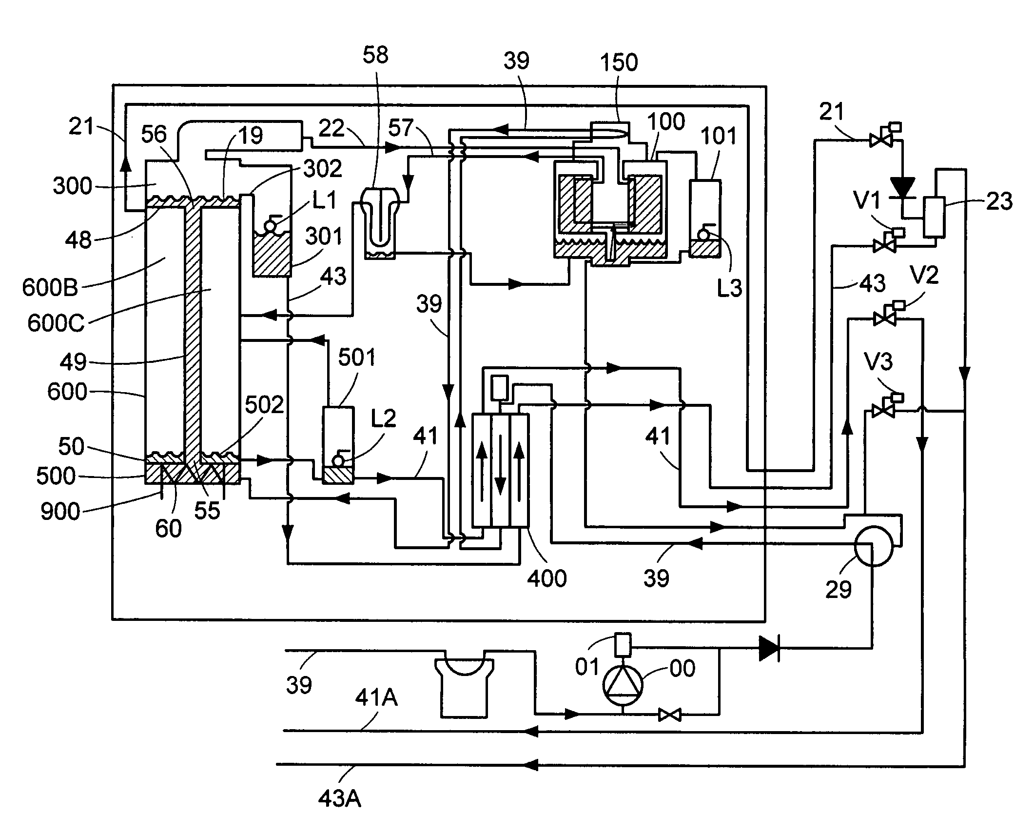
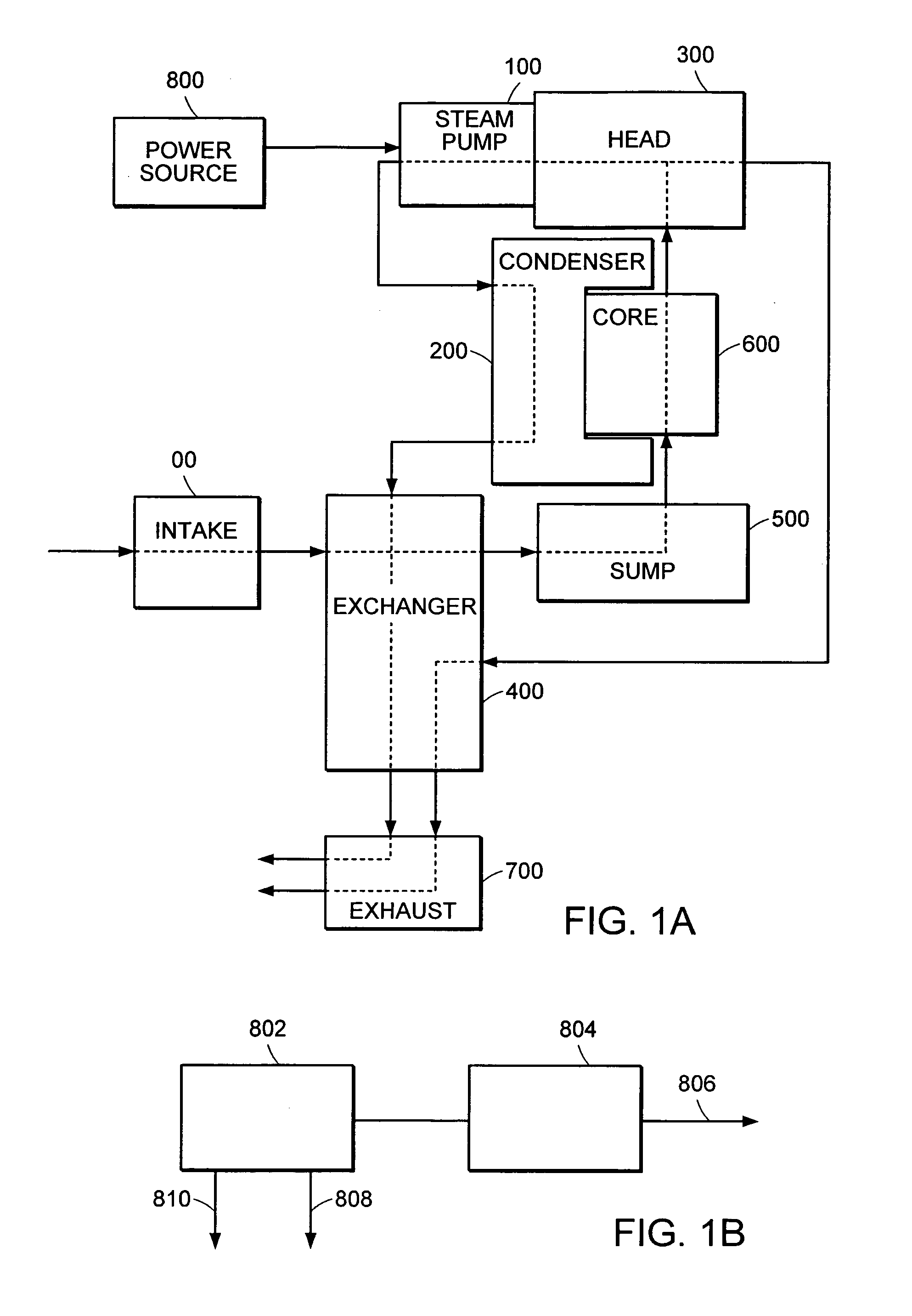
[0005]In a first embodiment of the invention there is provided a liquid purification system is provided that advantageously may be compact, inexpensive, and easily maintained. One embodiment has a distillation device with a liquid ring pump and a fully rotatable housing with a single continuous shaft about which the liquid ring pump, motor and rotor rotates, and a second shaft supporting the rotatable housing, with an internal or external combustion engine, preferably having motor rotor and magnets hermetically sealed within the fluid pressure boundary of the distillation system.
[0006]Another alternative embodiment has a distillation device with a liquid ring pump encased in a fully rotatable housing within the head vapor space of a still. Systemic heat sources can be redirected through a multi-line heat exchanger to maximize energy efficiency during the vaporization step. Back-wash lines may be directed to the intake from the head chamber of the evaporator / condenser, to keep unique flip-filters in the intake from fouling and to add heat into the heat exchange network. Further, a method of eliminating mist may be incorporated in the liquid ring pump component to eliminate contaminated liquid droplets entrained in the vapor and prevent them from being carried along to the condenser and thereby contaminating the purified product.
[0007]Another particular embodiment has a distillation device with a liquid ring pump and a fully rotatable housing with a single continuous shaft about which the liquid ring pump, motor and rotor rotates, and a second shaft supporting the rotatably housing, with an internal or external combustion engine and siphon pump in a lower reservoir to siphon liquid into the chamber of the liquid ring pump. The result is a highly efficient, easily accessed and maintained, relatively simple and inexpensive system for purifying a liquid.

Problems solved by technology

Many of these techniques are significantly affected by variations in the water quality and do not address a wide variety of common contaminants, such as bacteria, viruses, organics, arsenic, lead, mercury, and pesticides that can be found in water supplies in the developing world and elsewhere.
Moreover, some of these techniques are only well suited to centralized, large-scale water systems that require both a significant infrastructure and highly trained operators.
However, the poor financial resources, limited technical assets, and low population density that does not make it feasible to build centralized, large-scale water systems in much of the developing world, also limits the availability of adequate, affordable, and reliable power to operate vapor compression distillation systems, as well as hindering the ability to properly maintain such systems.

Method used


Image

  • Liquid ring pumps with hermetically sealed motor rotors
  • Liquid ring pumps with hermetically sealed motor rotors
  • Liquid ring pumps with hermetically sealed motor rotors

Examples


Embodiment Construction

[0059]Definitions. As used in this description and the accompanying claims, the following terms shall have the meanings indicated, unless the context otherwise requires.

[0060]The term “purifying” as used herein, and in any appended claims, refers to substantially reducing the concentration of one or more contaminants to less than or equal to specified levels or otherwise substantially altering the concentration of one or more contaminants to within a specified range.

[0061]The term “specified levels” as used herein refers to some desired level of concentration, as established by a user for a particular application. One instance of a specified level may be limiting a contaminant level in a fluid to carry out an industrial or commercial process. An example is eliminating contaminant levels in solvents or reactants to a level acceptable to enable an industrially significant yield in a chemical reaction (e.g., polymerization). Another instance of a specified level may be a certain contam...


PUM

PropertyMeasurementUnit
temperaturesaaaaaaaaaa
temperatureaaaaaaaaaa
pressureaaaaaaaaaa

Abstract

Embodiments of the invention are directed toward a novel pressurized vapor cycle for distilling liquids. In an embodiment of the invention, a liquid purification system is revealed, including the elements of an input for receiving untreated liquid, a vaporizer coupled to the input for transforming the liquid to vapor, a head chamber for collecting the vapor, a vapor pump with an internal drive shaft and an eccentric rotor with a rotatable housing for compressing vapor, a condenser in communication with the vapor pump for transforming the compressed vapor into a distilled product, and an electric motor with motor rotor and magnets hermetically sealed within the fluid pressure boundary of the distillation system.

Description

CROSS REFERENCE TO RELATED APPLICATIONS[0001]The present application is a regular application which claims priority from U.S. Provisional Patent Application 60 / 425,820, filed Nov. 13, 2002, U.S. Provisional Patent Application 60 / 490,615, filed Jul. 28, 2003, and the U.S. Provisional Patent 60 / 518,782, filed Nov. 10, 2003, each of which is hereby incorporated herein by reference.TECHNICAL FIELD[0002]The present invention relates to liquid purification, and more particularly to liquid purification by vapor compression distillation comprising a liquid ring pump with hermetically sealed motor rotors.BACKGROUND OF THE INVENTION[0003]A dependable source of clean water eludes vast segments of humanity. For example, the Canadian International Development Agency reports that about 1.2 billion people lack access to safe drinking water. Published reports attribute millions and millions of deaths per year, mostly children, to water related diseases. Many water purification techniques are well k...

Claims


Application Information

Patent Timeline
Patent Type & Authority Patents(United States)
IPC IPC(8): B01D3/42B01D1/28F04D29/00B01D1/06B01D1/22B01D3/10B01D5/00B01D29/01B01D35/12C02F1/16F04C19/00F04C29/00F28D7/00F28D9/00
CPCB01D1/0035B01D1/065B01D1/221B01D1/28B01D1/2887B01D1/289B01D1/2893B01D3/42B01D5/0015B01D29/01B01D35/12C02F1/048C02F1/16F04C19/002F04C19/004F04C19/005F04C19/008F04C29/0085F28D7/0066F28D9/005F28D9/0093B01D1/06B01D3/007B01D3/00C02F1/041B01D29/52B01D29/66B01D29/96C02F2301/08B01D3/10F04C2270/86Y02A20/212Y02E20/14B01D5/00C02F1/008C02F2201/009C02F2209/008F02G1/043F02G1/06F02G2243/00G05B15/02B01D1/0058B01D1/2896C02F2303/10G01F9/00
Inventor DEMERS, JASON A.LEONARD, SCOTT A.OWENS, KINGSTON
Owner DEKA PROD LLP
Learn More