Optical film and image display

a technology of optical film and image display, applied in the field of optical film, can solve the problems of narrow viewing angle, difficulty in obtaining perfect black viewing, retardation film conventionally known not being able to easily realize sufficient wide viewing angle, etc., and achieve the effect of easy viewing display and high contrast ratio

Active Publication Date: 2008-12-16
NITTO DENKO CORP
View PDF14 Cites 8 Cited by
  • Summary
  • Abstract
  • Description
  • Claims
  • Application Information

AI Technical Summary

Benefits of technology

[0007]The present invention aims at providing an optical film with a retardation film and a polarizing plate laminated together that may realize an easily viewable display with high contrast ratio in a wide range when applied to an image viewing display.
[0008]Furthermore, the present invention aims at providing an optical film that may provide a retardation value stabilized under conditions of high temperature or high humidity.
[0009]Moreover, the present invention aims at providing an image viewing display, especially a liquid crystal display operating in IPS mode, which can realize an easily viewable display and has a high contrast ratio in a wide range using the above-mentioned optical film.

Problems solved by technology

However, in TN mode, even if black viewing is performed, optical leakage resulting from birefringence caused by liquid crystal molecule near a substrate made it difficult to obtain perfect black viewing owing to driving characteristics thereof.
However, although almost perfect black viewing may be realized in normal direction to a panel in IPS mode, when a panel is observed in a direction shifted from normal direction, inevitable optical leakage occurs caused by characteristics of a polarizing plate in a direction shifted from an optical axis of the polarizing plates placed on upper and lower sides of the liquid crystal cell, as a result, leading to a problem of narrowing of a viewing angle.
However, retardation films conventionally known have not been able to easily realize sufficient wide viewing angles.
Thus, a retardation value of a retardation film used as a protective film would be shifted from a desired value, and a problem occurred that a stable effect could not be maintained.
However, a non-negligible retardation value of a TAC film makes design of a retardation film difficult that can compensate an axial shift.
Moreover, a dimensional variation of a polarizer caused under conditions of high temperature or high humidity varies a retardation value of a TAC film as mentioned above, thus a desired purpose cannot be attained.

Method used


Image

  • Optical film and image display
  • Optical film and image display
  • Optical film and image display

Examples


example 1

(Transparent Protective Film)

[0111]An alternating copolymer consisting of isobutene and N-methyl maleimide (N-methyl maleimide contents 50 mole %) 75 parts by weight, and an acrylonitrile-styrene copolymer having content of 28% by weight of acrylonitrile 25 parts by weight were dissolved in methylene chloride to obtain a solution having 15% by weight of solid content concentration. After this solution was poured on a polyethylene terephthalate film lay to cover a glass plate and was left at room temperature for 60 minutes, dried film was removed from the film concerned. The film obtained was dried for 10 minutes at 100° C., for 10 minutes at 140° C., and further for 30 minutes at 160° C. to obtain a transparent protective film having a thickness of 100 μm. The transparent protective film thus obtained showed an in-plane retardation Re2 of 4 nm and thickness direction retardation Rth of 4 nm.

(Polarizing Plate)

[0112]The above-mentioned transparent protective film was laminated to both...

example 2

[0117]A transparent protective film produced by a similar method as in Example 1 was stretched 1.5 times at 160° C. in an MD direction, and, subsequently stretched 1.5 times at 160° C. in a TD direction. This stretched film showed a thickness of 45 μm, an in-plane retardation Re2 of 4 nm, and a thickness direction retardation Rth of 12 nm.

[0118]Except that this transparent protective film was used, similar method as in Example 1 was repeated, and a polarizing plate and an optical film were produced. And, similar method as in Example was repeated to produce a liquid crystal display. In this liquid crystal display, a contrast ratio in a direction of gradient to make 70 degree from normal was measured in a direction to make an angle of 45 degrees to optical axes perpendicular to each other of polarizing plates to obtain a contrast ratio of 40. FIG. 5 shows a small color shift and excellent optical characteristics. And, after this liquid crystal display was maintained under condition of...

example 3

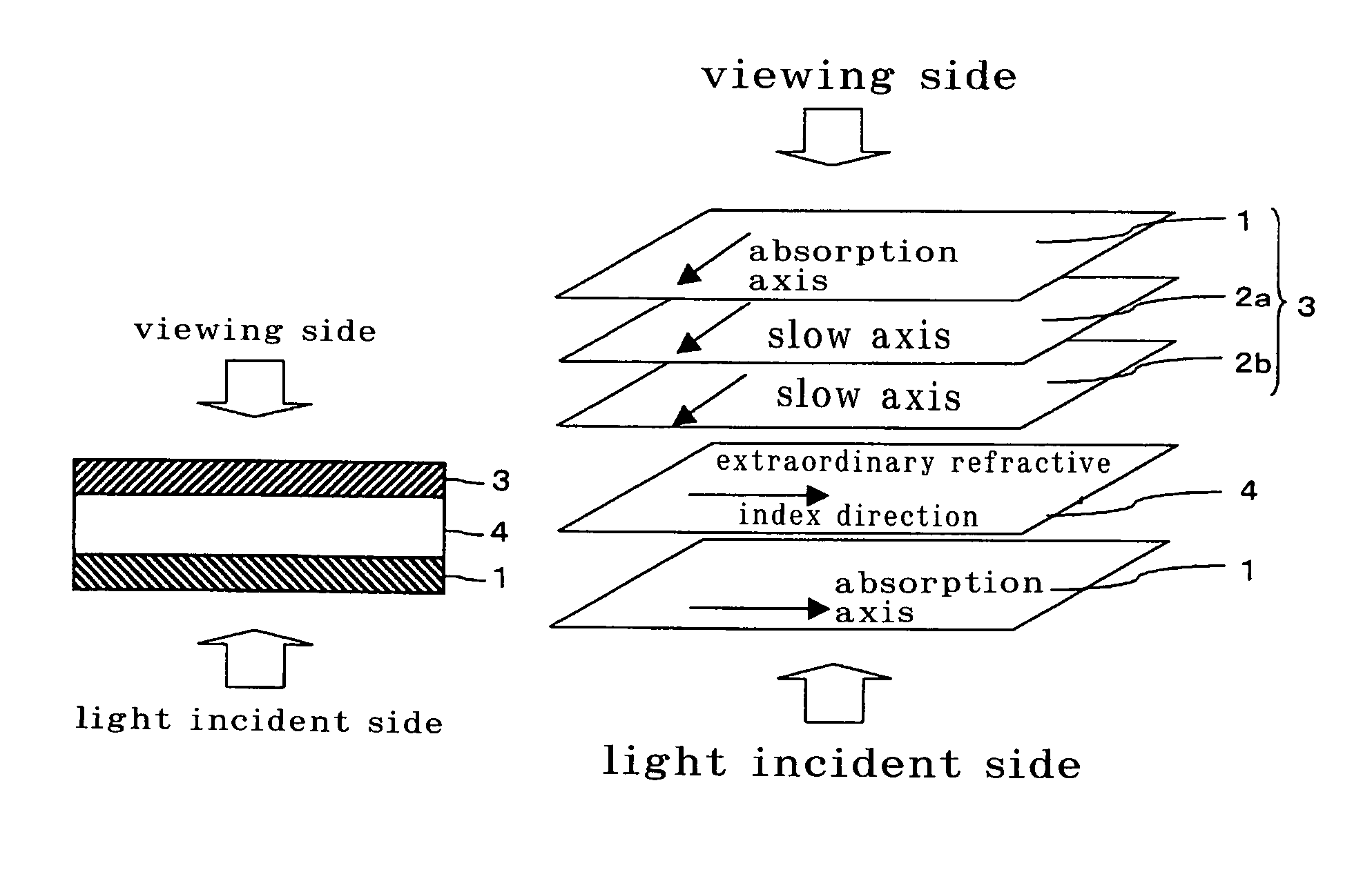
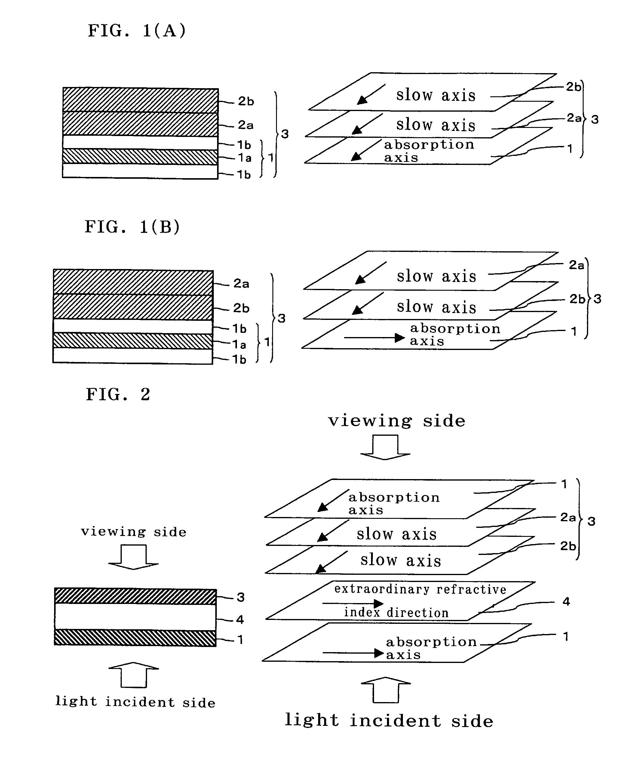
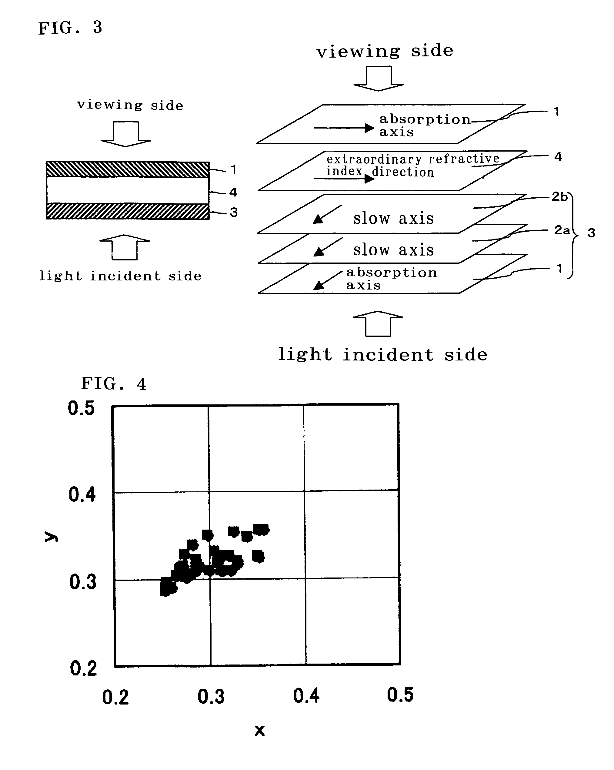
[0119]The two kind of retardation films (a) and (b) made of polycarbonate produced in Example 1 were directly laminated to a polarizer in the order of the retardation film (a) and the retardation film (b) so that the slow axes were parallel to the absorption axis of the polarizer to produce the optical film. Thus obtained optical film was laminated using a pressure sensitive adhesive so that a retardation film side was arranged on a face of a viewing side of a liquid crystal cell in IPS mode. On the other hand, a polarizing plate used in Example 1 was laminated to an opposite side using a pressure sensitive adhesive to produce a liquid crystal display.

[0120]In this liquid crystal display, a contrast ratio in a direction of gradient to make 70 degree from normal was measured in a direction to make an angle of 45 degrees to optical axes perpendicular to each other of polarizing plates to obtain a contrast ratio of 50. FIG. 6 shows a small color shift and excellent optical characterist...


PUM

PropertyMeasurementUnit
thickness direction retardationaaaaaaaaaa
thicknessaaaaaaaaaa
thicknessaaaaaaaaaa

Abstract

An optical film(3) of the invention comprises a polarizing plate(1) and plural retardation films(2) so that an absorption axis of the polarizing plate(1) is perpendicular or parallel to slow axes of the plural retardation films(2) and the slow axes of the plural retardation films(2) are parallel to one another. An Nz value expressed by Nz=(nx1−nz1) / (nx1−ny1) is in the range of from 0.15 to 0.85 and an in-plane retardation Re1 expressed by Re1=(nx1−ny1)×d1 is in the range of from 200 to 350 nm, where in each of the plural retardation films, a direction along with the refractive index in the film plane is maximum is defined as the X-axis, a direction perpendicular to the X-axis as the Y-axis, the thickness direction of the film as the Z-axis, and where refractive indices in each axial direction are defined as nx1, ny1, and nz1, respectively, and the thickness of the film as d1 (nm). The optical film may realize an easily viewable display with high contrast ratio in a wide range.

Description

TECHNICAL FIELD[0001]The present invention relates to an optical film in which a polarizing plate and plural retardation films are laminated. And the present invention relates to an image viewing display, such as a liquid crystal display, a PDP, and a CRT, using the above-mentioned optical film. Especially the optical film of the present invention is preferably used for a liquid crystal display operating in IPS mode.BACKGROUND ART[0002]Conventionally, as a liquid crystal display, there has been used a liquid crystal display in so-called TN mode in which a liquid crystal having a positive dielectric anisotropy is twisted and homogeneous aligned between substrates mutually facing to each other. However, in TN mode, even if black viewing is performed, optical leakage resulting from birefringence caused by liquid crystal molecule near a substrate made it difficult to obtain perfect black viewing owing to driving characteristics thereof. On the other hand, in a liquid crystal display in ...

Claims


Application Information

Patent Timeline
Patent Type & Authority Patents(United States)
IPC IPC(8): G02F1/1335G02B5/30G02F1/13363
CPCG02B5/3033G02B5/305G02B5/30
Inventor YANO, SHUUJIKINOSHITA, RYOUJIKAWAI, MASAYUKI
Owner NITTO DENKO CORP
Why Eureka
Try Eureka