Crop harvesting header with drive reversal

a technology of header and crop, applied in the direction of agricultural machines, agricultural tools and machines, mowers, etc., can solve the problems of adding to the complexity of the system, difficult therefore in the manufacturing system, and not being able to provide the conventional drain and filter system

Active Publication Date: 2008-12-23
MACDON INDS
View PDF12 Cites 30 Cited by
  • Summary
  • Abstract
  • Description
  • Claims
  • Application Information

AI Technical Summary

Problems solved by technology

Firstly it requires the provision of bi-directional pumps which adds to the complexity of the system.
It is difficult therefore in a manufacturing system to manufacture a tractor which has the option to omit the reversing system since all tractors will be manufactured with the bi-directional pumps regardless of the whether reversing option is selected or not.
Secondly, the bi-directional pumps require two directional flow in the circuit so that it is not possible to provide the conventional drain and filter system to reduce fluid contamination.
This is particularly problematic in a system where quick couplers are used since contamination is more likely leading to possible damage to the system.
The problems with this type of drive for a windrower tractor that is designed to quick disconnect from the header implement, therefore, are:
The possibility of contamination where typically these types of machines run the oil in a closed loop with a makeup supercharge pump providing makeup (clean) oil.
They also add shuttle valves to increase the makeup flow on the return side; however, typically this would only exchange 10% of the oil in order to have the contamination extracted from it.
If the machine has quick couplers on it, chances of introducing contamination is high.
This can be difficult to achieve consistently with a dual direction piston pump.
The limitations of reversing circuitry, since the dual direction pump is a closed loop pump, the reversing circuitry is limited to the drive system that it drives forward.
Reversing these components along with the main cutting / conditioning drive becomes a major challenge.

Method used


Image

  • Crop harvesting header with drive reversal
  • Crop harvesting header with drive reversal
  • Crop harvesting header with drive reversal

Examples


Embodiment Construction

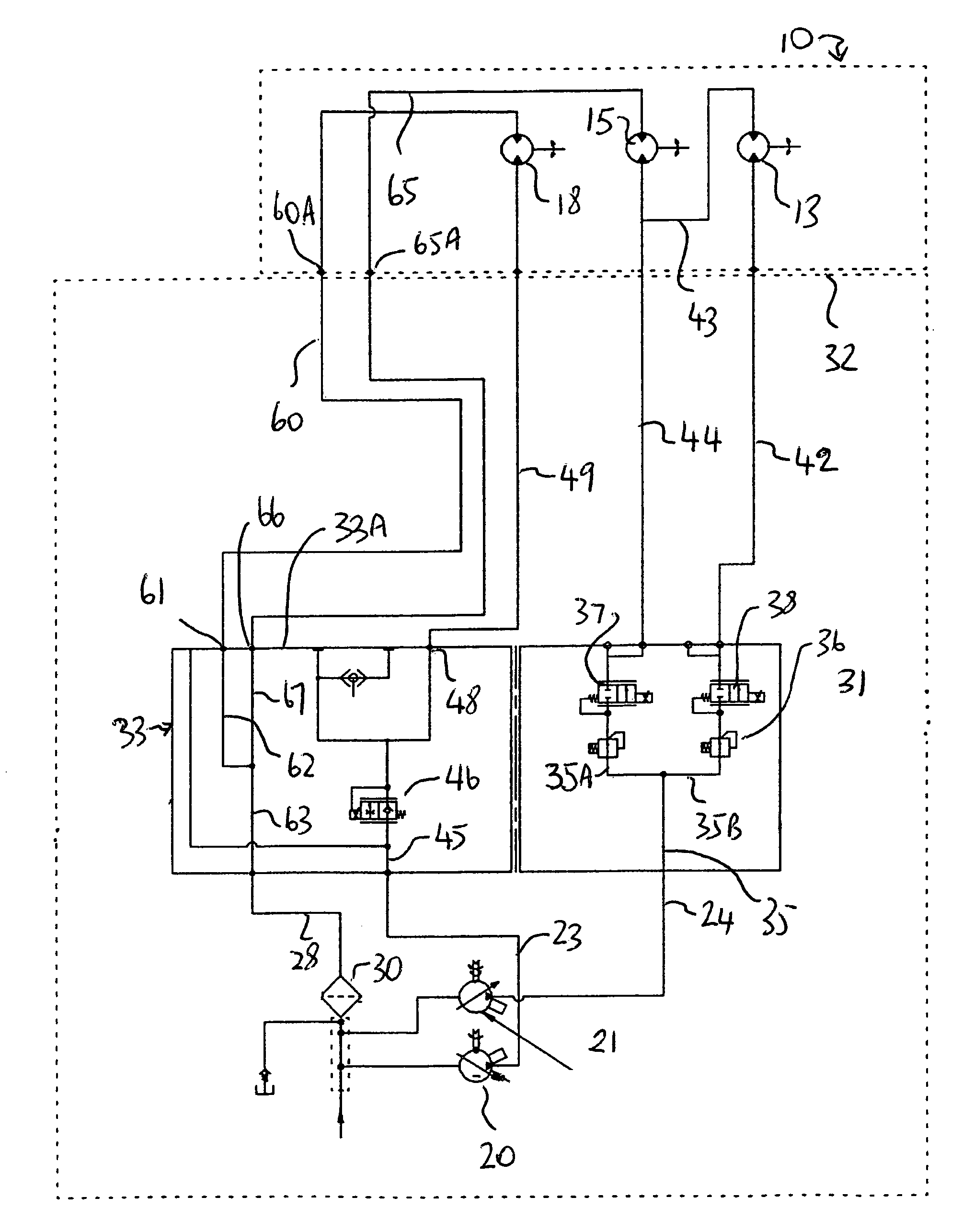
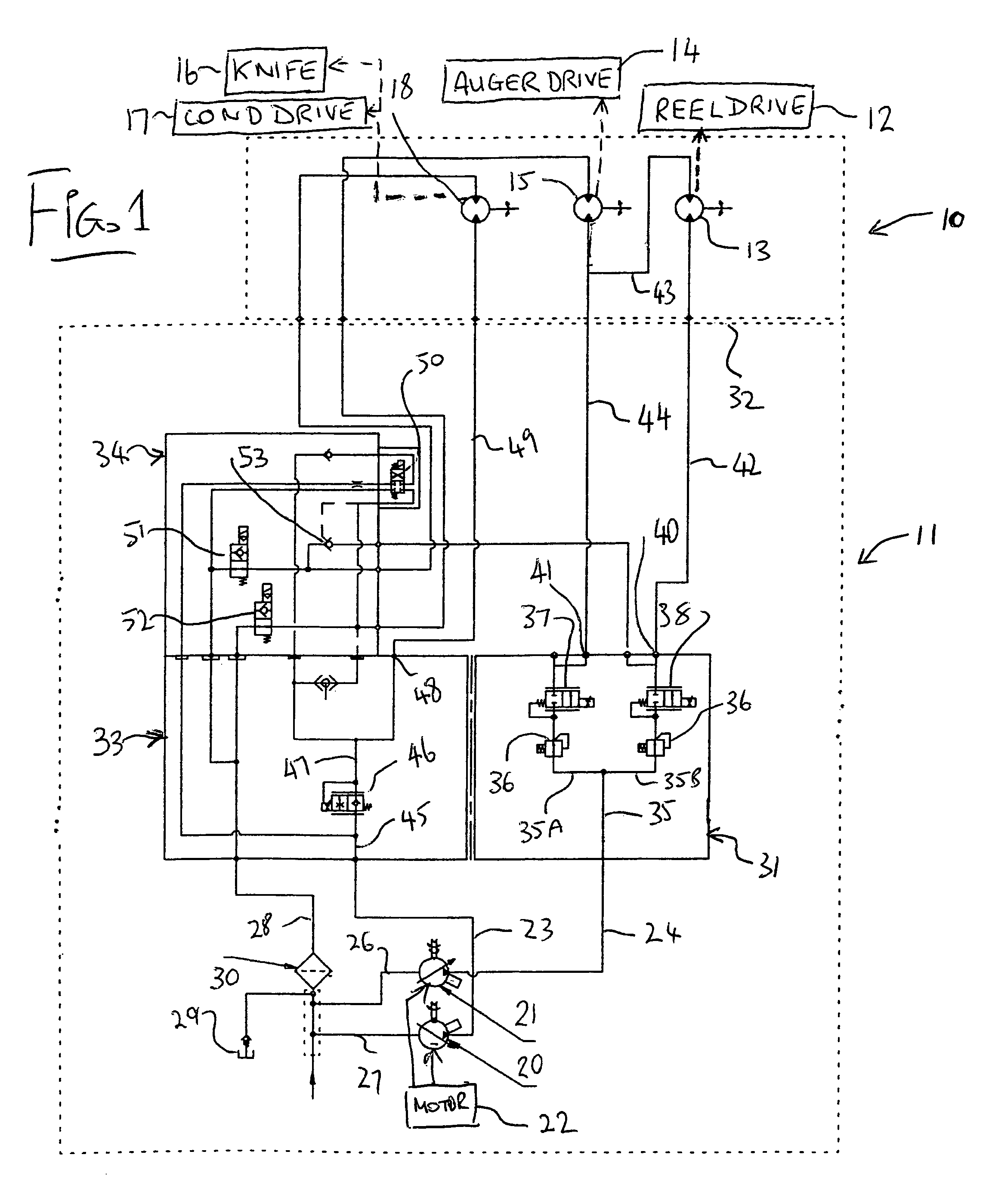
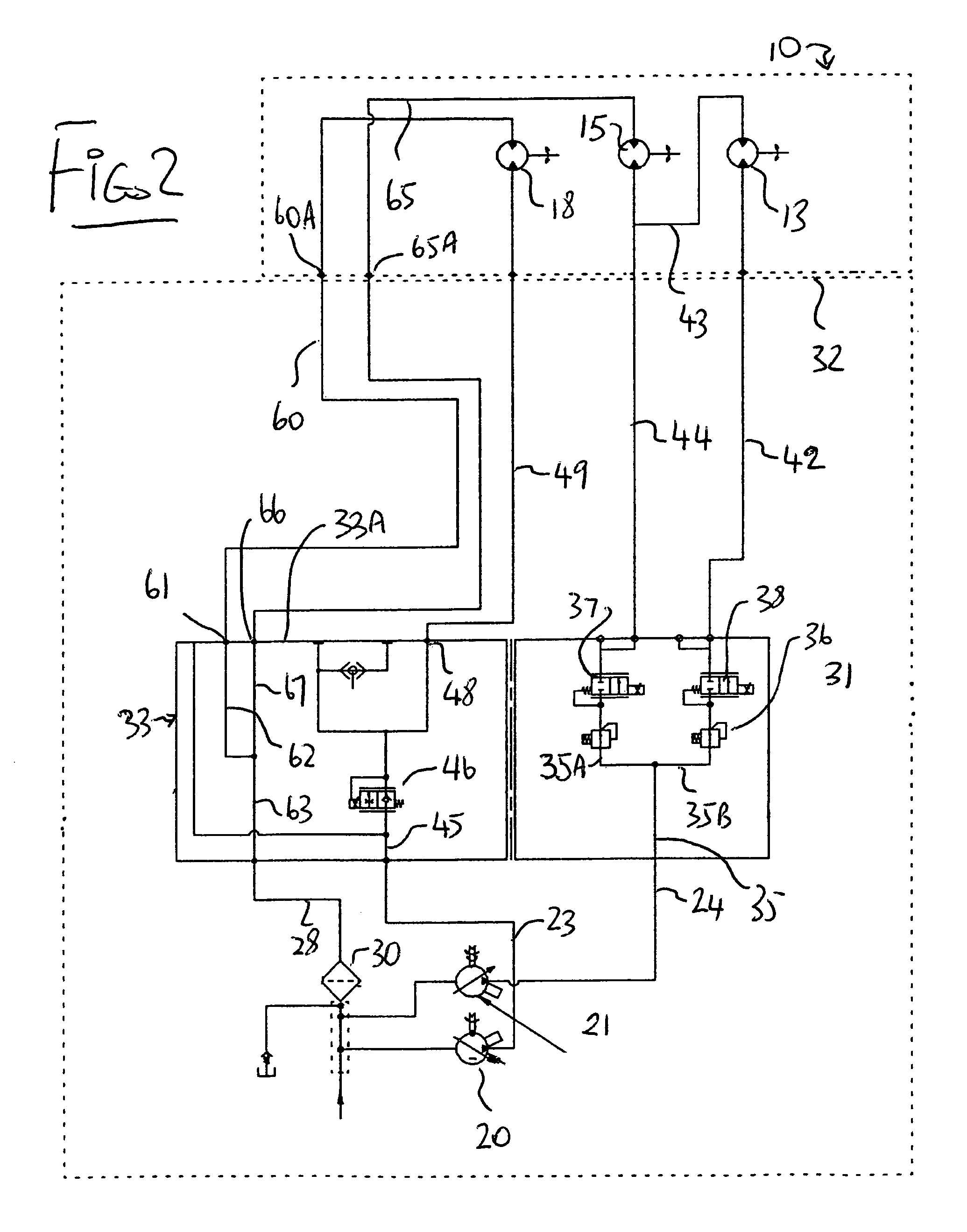
[0090]In FIG. 1 is shown the circuit for the crop harvesting machine which includes a header 10 and components mounted on a tractor 11. The construction of the tractor and header itself are not shown since these are well known to one skilled in the art and can vary in construction in accordance with well known parameters. It is suffice to say that the header includes a reel 12 driven by a reel motor 13, an auger 14 driven by an auger motor 15, a knife 16 and a conditioner 17 both driven by a drive motor 18.

[0091]The tractor 11 includes a first drive pump 20 and a second drive pump 21 each of which receives driving force from a motor 22 of the tractor. The pumps 20 and 21 are of the unidirectional type so that they provide pressurized flow only at an output side, receiving fluid at an inlet side from a drain line. The pump 20 thus has an output line 23 at which pressurized fluid is supplied and a pump 21 is an output line 24 for the pressurized fluid. Each of the pumps has a return l...


PUM


Abstract

A crop harvesting machine including a header mounted on a tractor is hydraulically driven by a pair of pumps on the tractor and a series of motors on the header. A first circuit control includes variable rate valves controlling the rate of supply of fluid from the unidirectional pumps to the motors to vary rate of the knife, conditioner, reel and converging systems in a forward harvesting direction. A second circuit controls reverse rotation of at least some of the elements for releasing a blockage by taking the fluid from one of the pumps and passing it through the separate second circuit to the required motors in series. The second circuit is provided in a separate block which can be omitted and thus constitutes an option. The drive of the motors in reverse direction in series ensures that they are driven at common speed without need from individual speed control. The use of unidirectional pumps and the separate circuits for forward and reverse allows the use of a single return and a filter at the return which is advantageous in a system which allows disconnection of couplings to allow the header to be replaced.

Description

[0001]This invention relates to a crop harvesting header and particularly to a drive system for the components of the header by which the direction of drive of at least some of the components can be reversed.BACKGROUND OF THE INVENTION[0002]MacDon, the Assignee of the present application, manufactures a tractor which is used to transport headers of different types across the ground for cutting a standing crop.[0003]Headers can be of various different types including headers known as “draper headers” in which there is provided a sickle knife across the front edge of the header which cuts the standing crop and a pair of conveyor belts or drapers behind the knife onto which the crop falls for transporting the crop transversely across the header to a discharge opening at a suitable location on the header. A reel is generally provided which rotates around an axis parallel to the knife above the knife and provides a series of bats which rotate and carry the cut crop over the knife and ont...

Claims


Application Information

Patent Timeline
Patent Type & Authority Patents(United States)
IPC IPC(8): A01D69/00
CPCA01B71/06A01D43/105
Inventor MACGREGOR, DON
Owner MACDON INDS
Why Eureka
Try Eureka