Apparatus for electromagnetically forming a workpiece
a technology of electromagnetic forming and workpiece, which is applied in the direction of forging/pressing/hammering apparatus, manufacturing tools, forging presses, etc., can solve the problems of material failure and material warpage, material failure, such as tearing, and material failure, so as to facilitate electromagnetic forming of workpieces and improve workpiece quality
- Summary
- Abstract
- Description
- Claims
- Application Information
AI Technical Summary
Benefits of technology
Problems solved by technology
Method used
Image
Examples
first embodiment
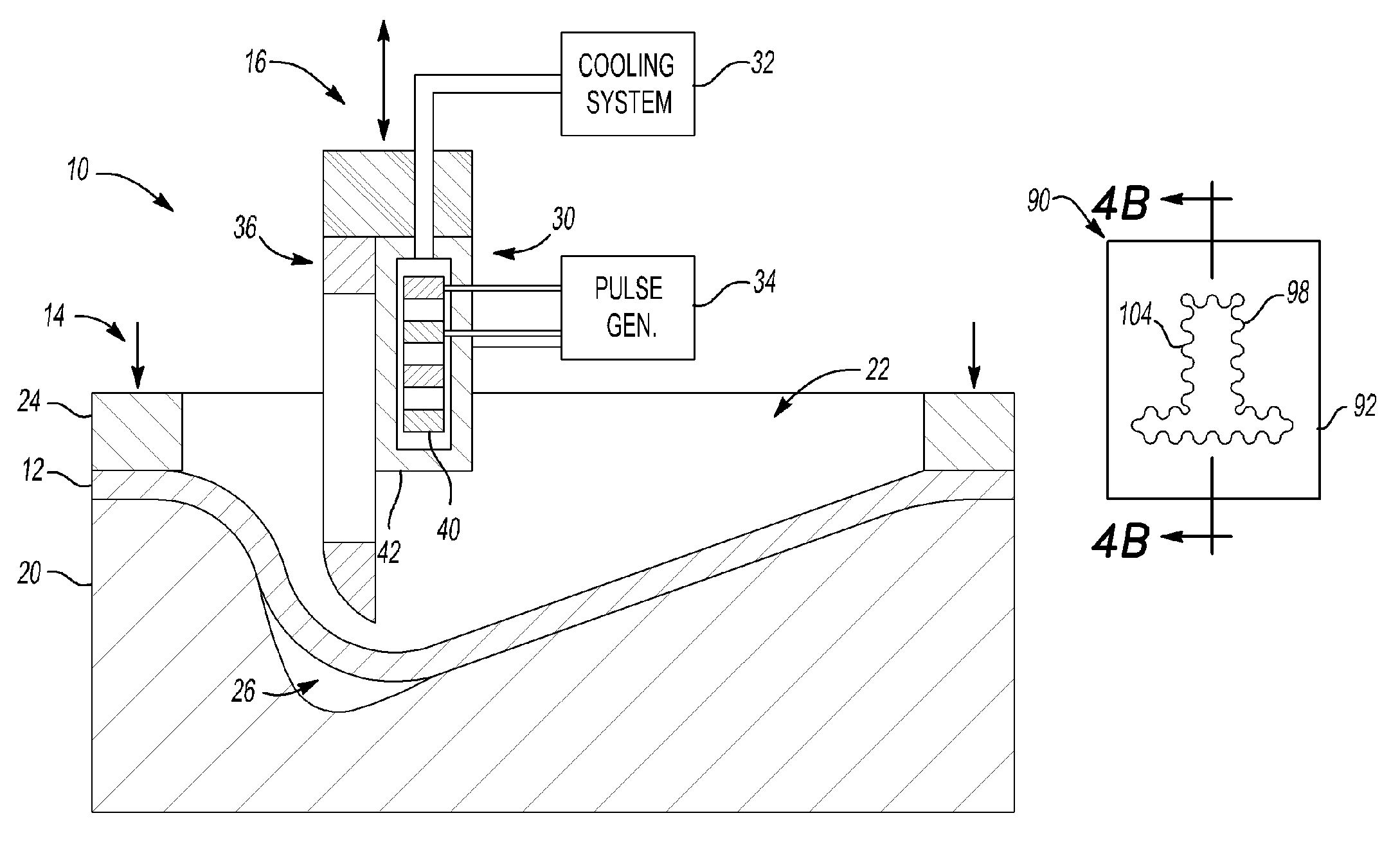
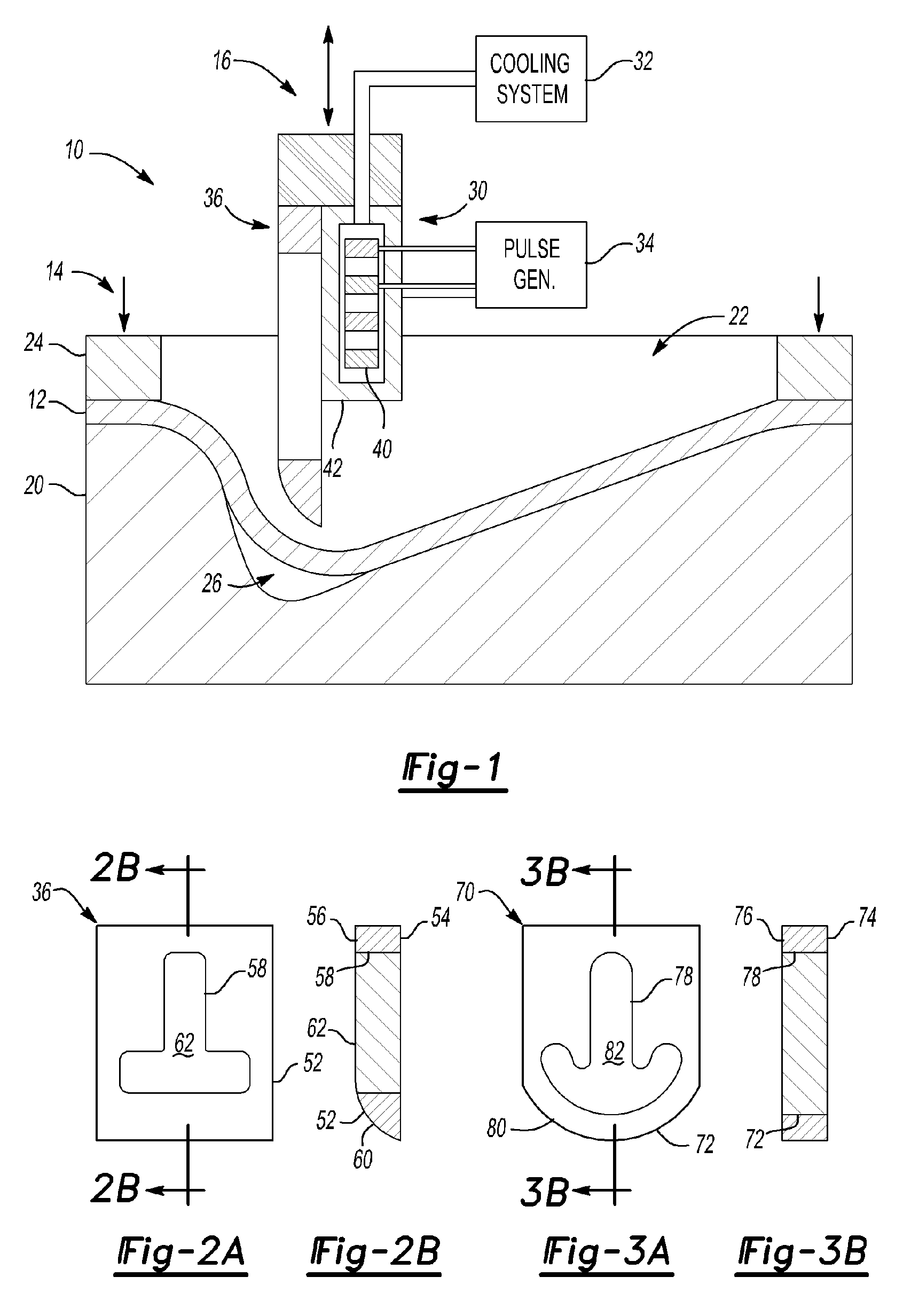
[0028]Referring to FIGS. 1, 2a and 2b, the forming tool 36 is shown. In the embodiment shown, the forming tool 36 includes an electrically conductive body 52 having a first surface 54, a second surface 56 disposed opposite the first surface 54, an aperture 58 extending between the first and second surfaces 54, 56, and an end surface 60 for applying or concentrating electromagnetic force toward the workpiece. The aperture 58 is shown having a generally inverted T-shape in which the top of the “T” is oriented toward the end surface 60. The T-shape helps increase the current flow path through the electrically conductive body 52. An insulator 62 may be disposed in the aperture 58 and may help improve the strength and durability of the forming tool 36.
second embodiment
[0029]Referring to FIGS. 3a and 3b, the forming tool 70 is shown. In this embodiment, the forming tool 70 includes an electrically conductive body 72 having a first surface 74, a second surface 76 disposed opposite the first surface 74, an aperture 78 extending between the first and second surfaces 74, 76, and a curved end surface 80. The aperture 78 is shown having a generally inverted T-shape in which the top of the “T” is oriented toward the curved end surface 80 and curved in generally the same manner as the curved end surface 80. An insulator 82 may be disposed in the aperture 78 and may help improve tool strength and durability as previously described.
third embodiment
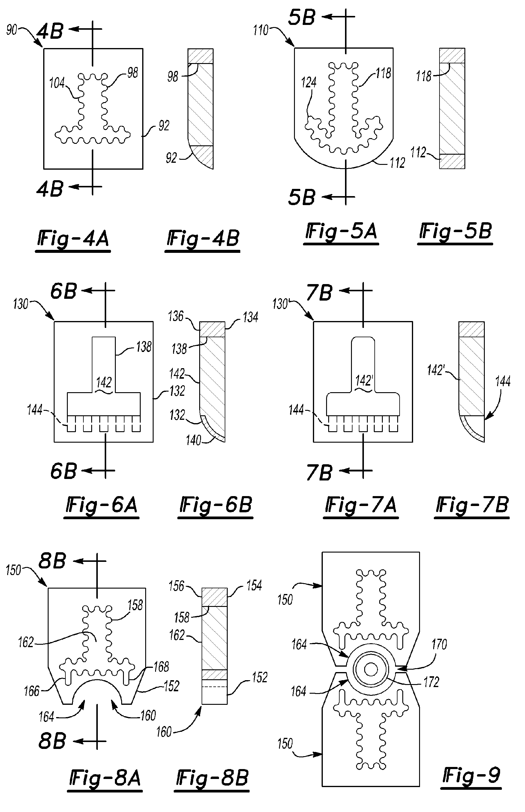
[0030]Referring to FIGS. 4a and 4b, the forming tool 90 is shown. In this embodiment, the electrically conductive body 92 has a generally T-shaped aperture 98 as previously described with respect to FIGS. 2a and 2b. In addition, the aperture 98 is defined by a wavy or serpentine wall 104 that includes a plurality of curved surfaces. The serpentine wall 104 may increase the current flow path through the body 92 and its working surface that faces the workpiece 12 to a greater amount than a generally linear wall to help improve electromagnetic forming quality and efficiency. The serpentine wall 104 may be provided around the entire aperture 98 or a portion thereof in various embodiments of the present invention.
PUM
| Property | Measurement | Unit |
|---|---|---|
| electromagnetic pressure | aaaaa | aaaaa |
| electromagnetic field | aaaaa | aaaaa |
| pressure | aaaaa | aaaaa |
Abstract
Description
Claims
Application Information
 - R&D
- Intellectual Property
- Life Sciences
- Materials
- Tech Scout
- Unparalleled Data Quality
- Higher Quality Content
- 60% Fewer Hallucinations
Browse by: Latest US Patents, China's latest patents, Technical Efficacy Thesaurus, Application Domain, Technology Topic, Popular Technical Reports.
© 2025 PatSnap. All rights reserved.Legal|Privacy policy|Modern Slavery Act Transparency Statement|Sitemap|About US| Contact US: help@patsnap.com


