Apparatus for transporting a sensor

a sensor and apparatus technology, applied in the field of sensors, can solve the problems that the above described apparatus is not suitable for all subsurface imaging applications, and the cart is not suitable, so as to improve obstacle avoidance, cushion sensor movement, and speed up the effect of speed

Active Publication Date: 2008-12-23
SENSORS & SOFTWARE
View PDF20 Cites 6 Cited by
  • Summary
  • Abstract
  • Description
  • Claims
  • Application Information

AI Technical Summary

Benefits of technology

[0008]It is an object of the present invention to provide an improvement over the prior art. It is a further object of the present invention to provide an apparatus for transporting a sensor which is capable of being deployed at high speeds and long distances. It is a further object of the invention to provide an apparatus for transporting a sensor which is capable of improved obstacle avoidance and cushioning sensor movement without unduly removing the sensor outside the operational distance. This advantage is particularly desirable when the sensor is transported at high speed, where a collision with an obstacle on the target surface or constant jarring may damage the sensor.
[0009]It is a further object of the invention to provide faster and simpler adjustability of the sensing surface to different operational distances. This advantage may be provided by maintaining the angle between the sensing surface and the struts at less than 90°, thereby limiting the sensor's downward movement.
[0011]According to a second aspect of the invention, an apparatus for transporting a sensor having a sensing surface at an operational distance from a target surface is provided. The apparatus comprises: a) an upper frame; b) a front strut defining an upper end and a lower end, the upper end of the front strut being pivotally connected to the upper frame, the lower end of the front strut being pivotally connected to the sensor; c) a rear strut defining an upper and a lower end, the rear strut being spaced apart from the front strut and substantially parallel thereto, the upper end of the rear strut being pivotally connected to the upper frame, the lower end of the rear strut being pivotally connected to the sensor; and d) a deflector connected to one of the front strut, the rear strut, and the sensor. The deflector is located forward of the sensor and spaced apart therefrom. The deflector defines a deflection surface. Upon the deflection surface impacting the obstacle on the target surface, the deflector is adapted to pivot the struts upwardly, thereby avoiding collision of the sensing surface with the obstacle.

Problems solved by technology

However, the cart described above is not suitable for all subsurface imaging applications.
For example, the cart is not suitable for applications which require the sensor to travel long distances or at high speeds, such as when the sensor is towed behind motorized vehicles.

Method used


Image

  • Apparatus for transporting a sensor
  • Apparatus for transporting a sensor
  • Apparatus for transporting a sensor

Examples


Embodiment Construction

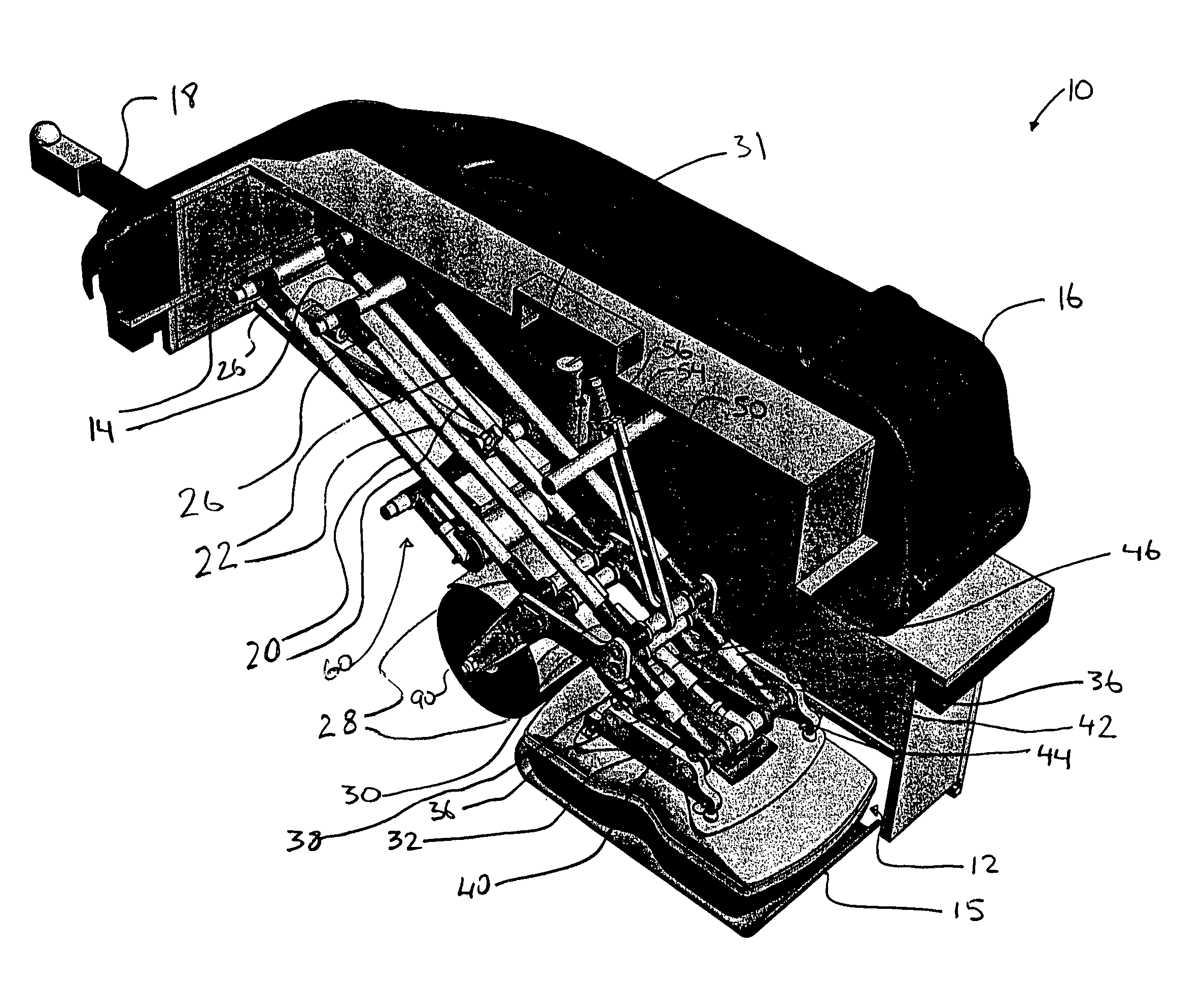
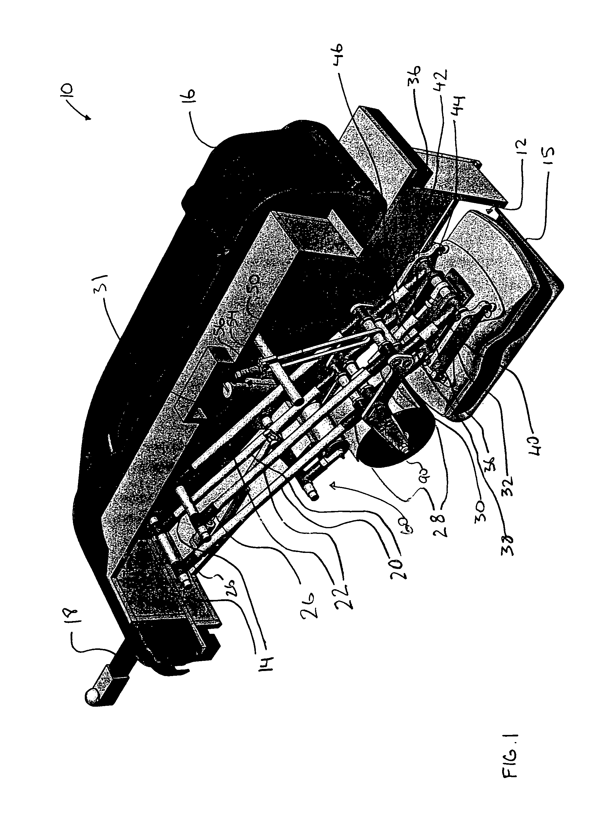
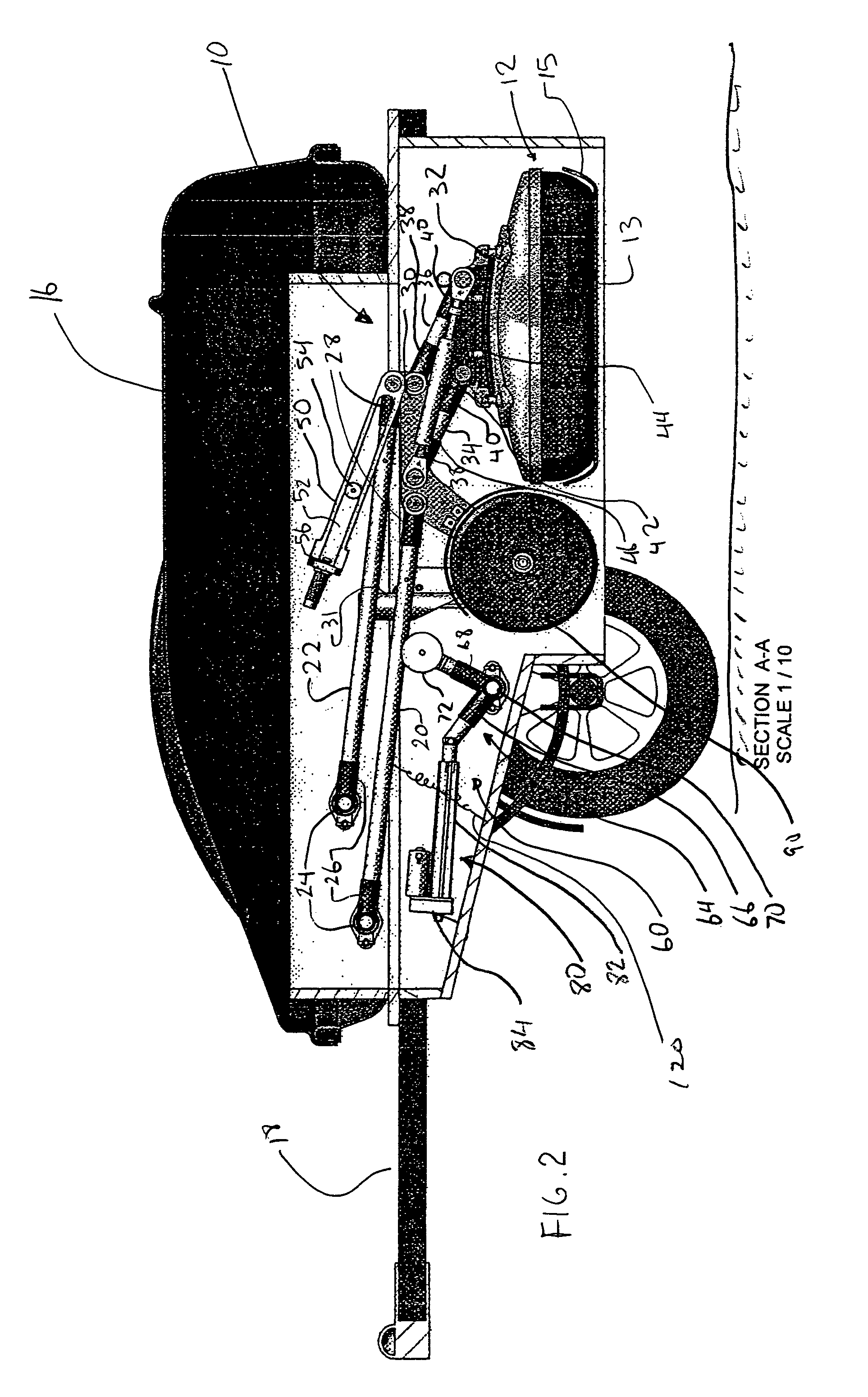
[0026]FIGS. 1-6 show an apparatus 10 for transporting and stabilizing a sensor 12, according to a preferred embodiment of the present invention. The sensor 12 is preferably a conventional GPR radar sensor assembly. The sensor 12 includes a planar sensing surface 13 protected by a skid plate 15. When in a deployed position, the sensing surface 13 is positioned at an operational distance d (best shown in FIG. 3) from the target surface 17 (such as a ground or road surface, or a tunnel wall or ceiling) when deployed for imaging. The operational distance d is a function of GPR frequency and actual surface roughness, and may range from about 2 mm to about 20 cm. Typical settings are about 3-10 mm for high frequency sensors and about 10-20 mm for low frequency sensors. It will be understood by those skilled in the art that, for certain applications where the target surface 17 is extremely rough or a lower resolution scan is acceptable, the sensor may be located much higher from the target...


PUM


Abstract

An apparatus for transporting a sensor having a sensing surface at an operational distance from a target surface is disclosed. The apparatus includes an upper frame and spaced apart parallel front and rear struts. The upper ends of the struts are connected to the upper frame. The lower ends of the struts are connected to the sensor. The front and rear struts pivot about the upper frame to move the sensor in response to an obstacle on the target surface, The sensor pivots about the lower ends of the front and rear struts to maintain the sensing surface in substantially parallel orientation to the target surface. The angle between the sensing surface and the front and rear struts is less than 90°.

Description

[0001]This is an application claiming the benefit under 35 USC 119(e) of U.S. Application Ser. No. 60 / 590,925 filed Jul. 26, 2004. U.S. Application Ser. No. 60 / 590,925; Canadian Application Serial No. 2,473,266 filed Jul. 8, 2004; and, Canadian Application Serial No. 2,473,292 filed Jul. 7, 2004 are incorporated herein, in their entirety, by this reference to them.FIELD OF THE INVENTION[0002]The invention relates to sensors, including without limitation sensors for subsurface imaging. In particular, the invention relates to an apparatus for transporting a sensor and positioning the sensor during travel over a target area.BACKGROUND OF THE INVENTION[0003]Subsurface imaging is widely used in many fields, such as archeology, forensic sciences, geotechnical and environmental engineering, and construction. Subsurface imaging is conducted using any number of known imaging technologies. One such technology is ground penetrating radar (GPR).[0004]When GPR is used, the imaging is accomplishe...

Claims


Application Information

Patent Timeline
Patent Type & Authority Patents(United States)
IPC IPC(8): B62D63/00
CPCG01V3/15G01S13/885Y10S414/13
Inventor LEGGATT, CHARLES DAVID
Owner SENSORS & SOFTWARE
Why Eureka
Try Eureka