Priority setting scheme for a wireless terminal

a wireless terminal and priority setting technology, applied in the field of priority setting schemes for wireless terminals, can solve the problems of increasing the complexity of routing them in the board, severe performance degradation, and increasing the board size, and achieve the effect of greater granularity

Active Publication Date: 2008-12-23
STMICROELECTRONICS INT NV
View PDF6 Cites 32 Cited by
  • Summary
  • Abstract
  • Description
  • Claims
  • Application Information

AI Technical Summary

Benefits of technology

[0012]An advantage of the present invention is that there is no requirement to increase the number of pins of the chips used for implementation.
[0013]A first aspect of the present invention provides a method of operating a first wireless transceiver unit which operates in the same portion or has an overlapping portion of an RF spectrum as a second wireless transceiver unit, there being an arbitration device which controls when the first and second wireless transceiver units can access the shared portion of the RF spectrum and an interface connecting the first transceiver unit to the arbitration device, the interface carrying access requests, each request having one of N possible interface priority levels, the method comprising:
[0014]associating a transceiver priority level with a series of packets which are intended for transmission, the transceiver priority level being chosen from a range of M possible priority levels, where M>N; and
[0015]sending a sequence of access requests to the arbitration device, each access request in the sequence having an interface priority level chosen from the range of N possible interface priority levels, wherein the average value of the interface priority levels used in the sequence depends on the associated transceiver priority level.
[0016]By associating a priority level taken from a range of M possible levels, the first transceiver unit is able to provide a greater degree of granularity to its requests. For high priority traffic, the transceiver unit can continue to send a sequence of access requests to the arbitration unit with the highest of the N possible interface priority levels. However, other traffic which is of a lower priority, but which must be sent on an occasional basis (such as periodic traffic for maintaining synchronization) can be associated with a priority level at the transceiver which will send an occasional access request at the highest one of the N interface priority levels.
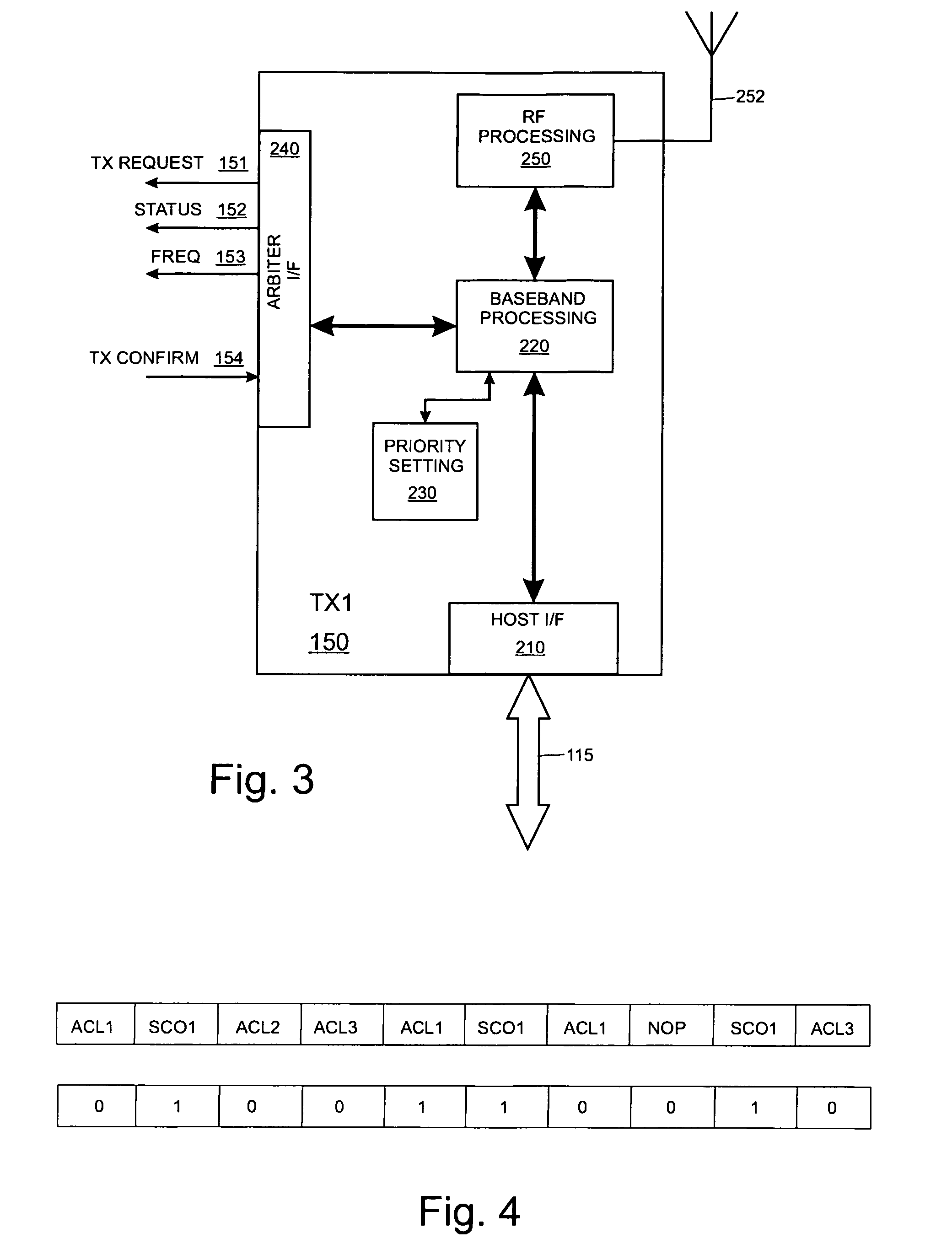
[0017]In one embodiment the interface between the first transceiver unit and the arbitration device supports a high priority level and a low priority level (N=2) and the number of high priority level access requests sent during the sequence corresponds to the associated transceiver priority level.

Problems solved by technology

Since both IEEE 802.11 and IEEE 802.15.1 operate in the same 2.4 GHz unlicensed frequency band, there is mutual interference between the two wireless systems which may result in severe performance degradation.
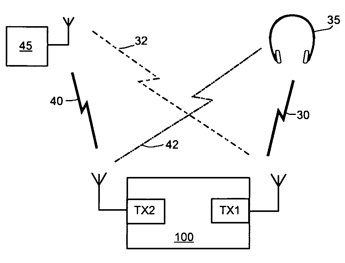
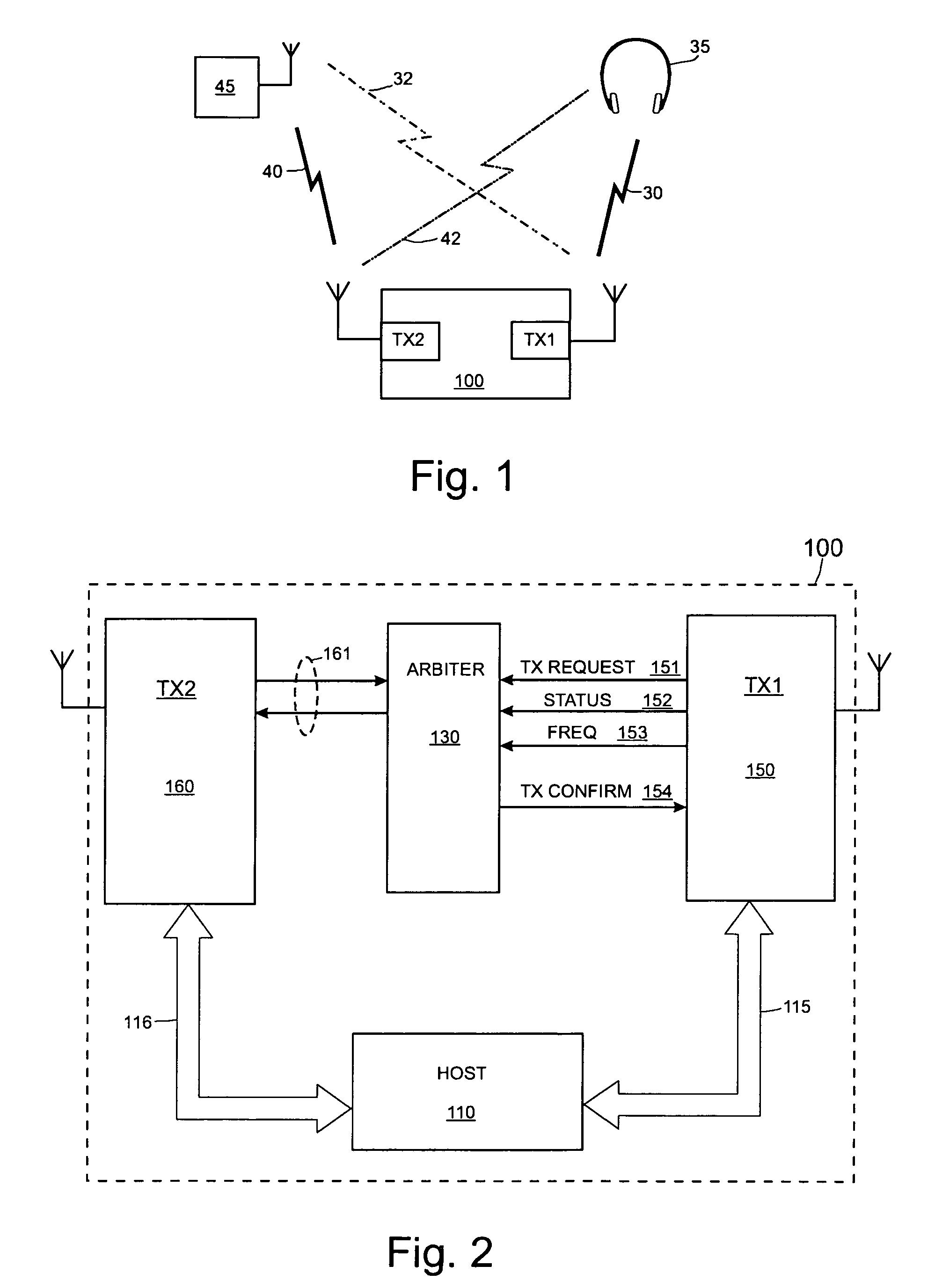
The recommended interface between a WPAN transceiver and an arbitration unit is shown in FIG. 2 as lines 151-154.The Bluetooth device and the WLAN may not be placed really close to each other (maybe 10 cm distance) in this case increasing the number of the pin in the coexistence interface increase the complexity of routing them in the board and most likely it increases the board size.The pin count of both chips will increase and this is a problem especially for the Bluetooth which is a very small chip and there is very little room for adding pins.
One problem with this arrangement is that, during a long period of WLAN activity, such as a file transfer, the WPAN links with priority ‘0’ will be refused.
In an environment where the Bluetooth device shares the RF band with a WLAN, this can be difficult.

Method used


Image

  • Priority setting scheme for a wireless terminal
  • Priority setting scheme for a wireless terminal
  • Priority setting scheme for a wireless terminal

Examples


Embodiment Construction

[0030]The present invention will now be described with reference to certain embodiments and with reference to the above mentioned drawings. Such description is by way of example only and the invention is not limited thereto. In particular the present invention will be described with reference to radio communications network but the present invention is not limited thereto. The term “wireless” should be interpreted widely to cover any communications system which does not use fixed wireline communications for some of its transmissions. Alternative wireless communications systems include optical systems such as those operating with diffuse infra-red. It should also be noted that the term “wireless” also includes so-called cordless systems. General aspects of cordless communications systems are described for instance in the book by W. Tuttlebee, “Cordless Telecommunications Worldwide”, Springer, 1997. Cordless systems are generally local, uncoordinated radio communications networks havi...


PUM


Abstract

First and second wireless transceiver units operate in the same portion of the RF spectrum. An arbitration device controls when the first and second wireless transceiver units can operate. An interface connects the first transceiver unit to the arbitration device and receives requests for operation. The interface permits the transceiver unit o use one of N possible priority levels for requests. The transceiver associates a transceiver priority level to a series of packets which is chosen from a range of M possible priority levels. The transceiver unit sends a sequence of requests to operate to the arbitration device, each request in the sequence having a priority level chosen from the range of N possible priority levels. The average value of the priority levels used in the sequence depends on the associated transceiver priority level.

Description

FIELD OF THE INVENTION[0001]This invention relates to methods and devices for setting a priority level in a wireless communication apparatus as well to telecommunications systems using the methods and devices and software for use with the methods and devices.BACKGROUND TO THE INVENTION[0002]One band of the RF spectrum which is being increasingly used for wireless communications is the unlicensed Industrial Scientific & Medical (ISM) band at 2.4 GHz. Currently, two types of wireless technology operate in this part of the spectrum.[0003]Firstly, there is Wireless Local Area Network (WLAN) technology which is standardized under IEEE 802.11. One variant of IEEE 802.11 uses a frequency-hopping spread spectrum (FHSS) technique with 1 MHz channel separation and pseudorandom hops across 79 channels. Another variant (IEEE 802.11b) uses direct sequence spread spectrum (DSSS) techniques, with 22 MHz channels. WLAN technology is widely used in offices, homes and public places to support network...

Claims


Application Information

Patent Timeline
Patent Type & Authority Patents(United States)
IPC IPC(8): H04Q7/00H04B7/212H04L12/28H04L12/56H04W16/14H04W72/12H04W74/00H04W88/06
CPCH04W72/1215H04W72/1242H04W74/00H04W88/06H04W72/569
Inventor CAPRETTA, PIETRO
Owner STMICROELECTRONICS INT NV
Why Eureka
Try Eureka