Floor mop

a technology for mop and floor, applied in carpet cleaners, cleaning machines, cleaning equipment, etc., can solve the problem of requiring a lower water level for a complete immersion of the mop in the cleaning water

Inactive Publication Date: 2008-12-30
CARL FREUDENBERG KG
View PDF24 Cites 16 Cited by
  • Summary
  • Abstract
  • Description
  • Claims
  • Application Information

AI Technical Summary

Benefits of technology

[0018]The guide surface preferably slopes down towards the mop supporting wing on the side of the elevation facing the free end of the plate. It is thereby achieved that the force to be applied to the squeezing slider after passing over the elevations decreases at the end of the squeezing process and thus gives the user a clear indication that the squeezing process has been completely accomplished and terminated.

Problems solved by technology

The sloping arrangement of the one side edge and the consequent deviation from a rectangular surface of the mop supporting wing has the result that a lower water level is required for a complete immersion of the mop in the cleaning water.

Method used


Image

  • Floor mop
  • Floor mop
  • Floor mop

Examples


Embodiment Construction

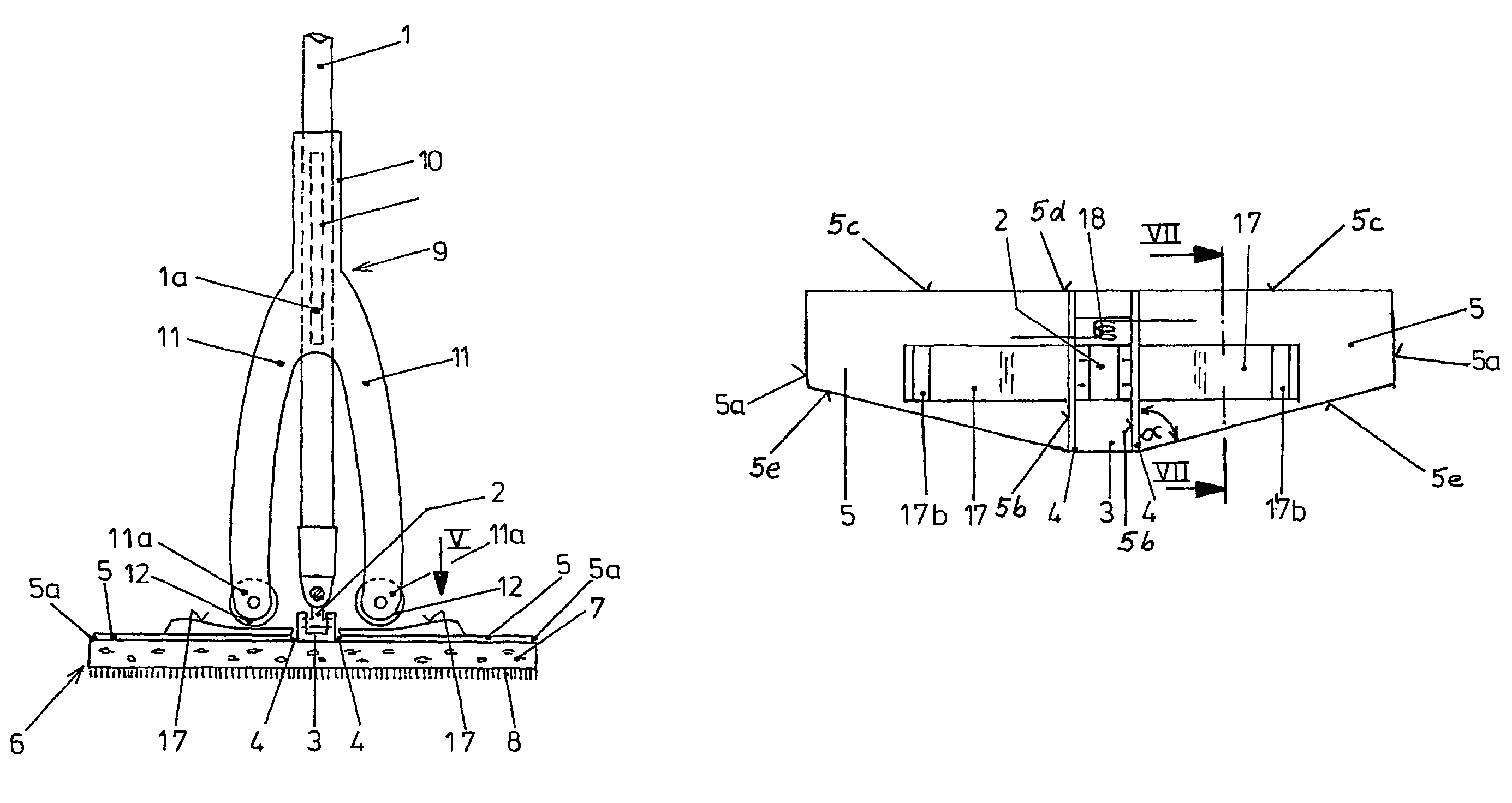
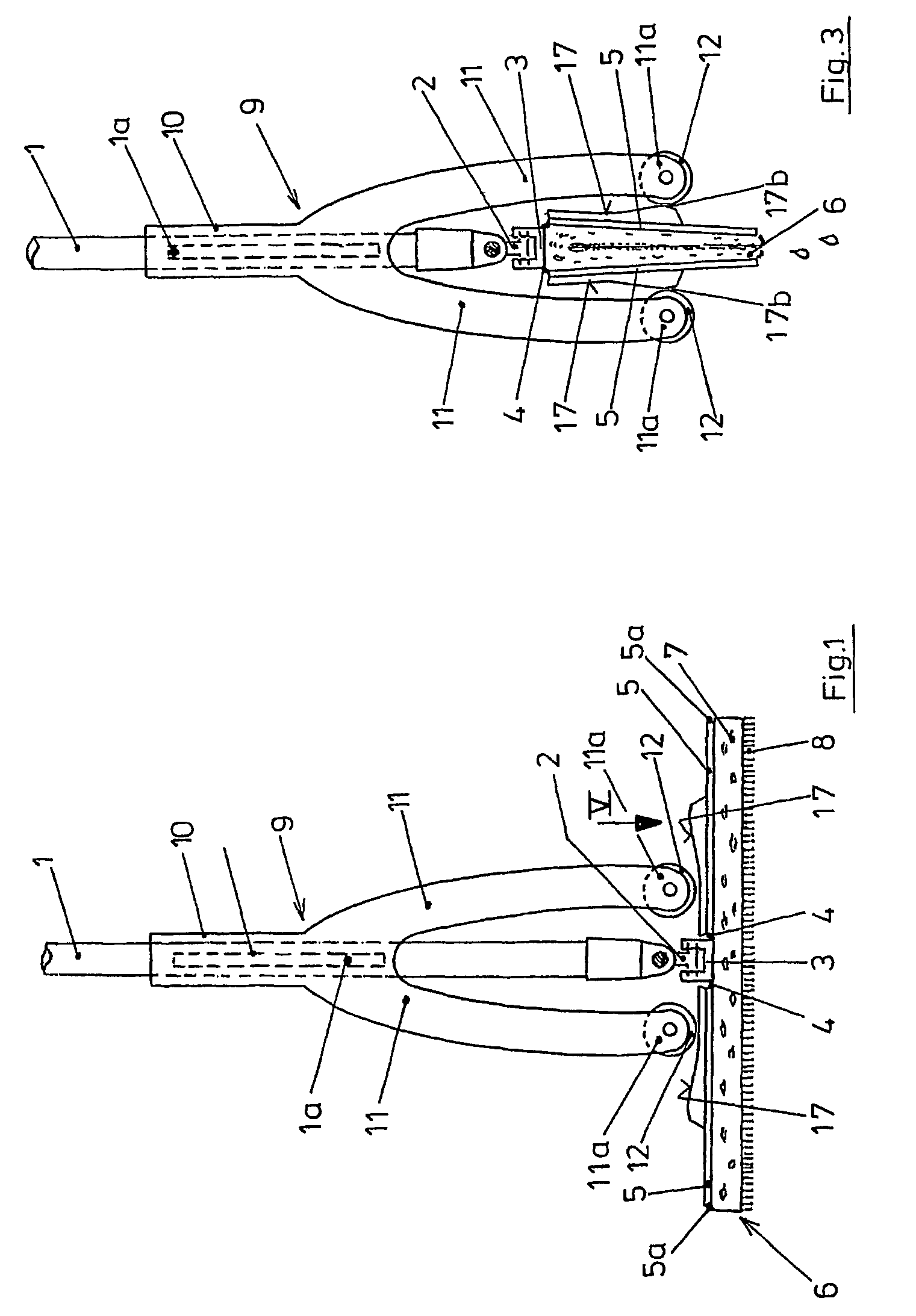
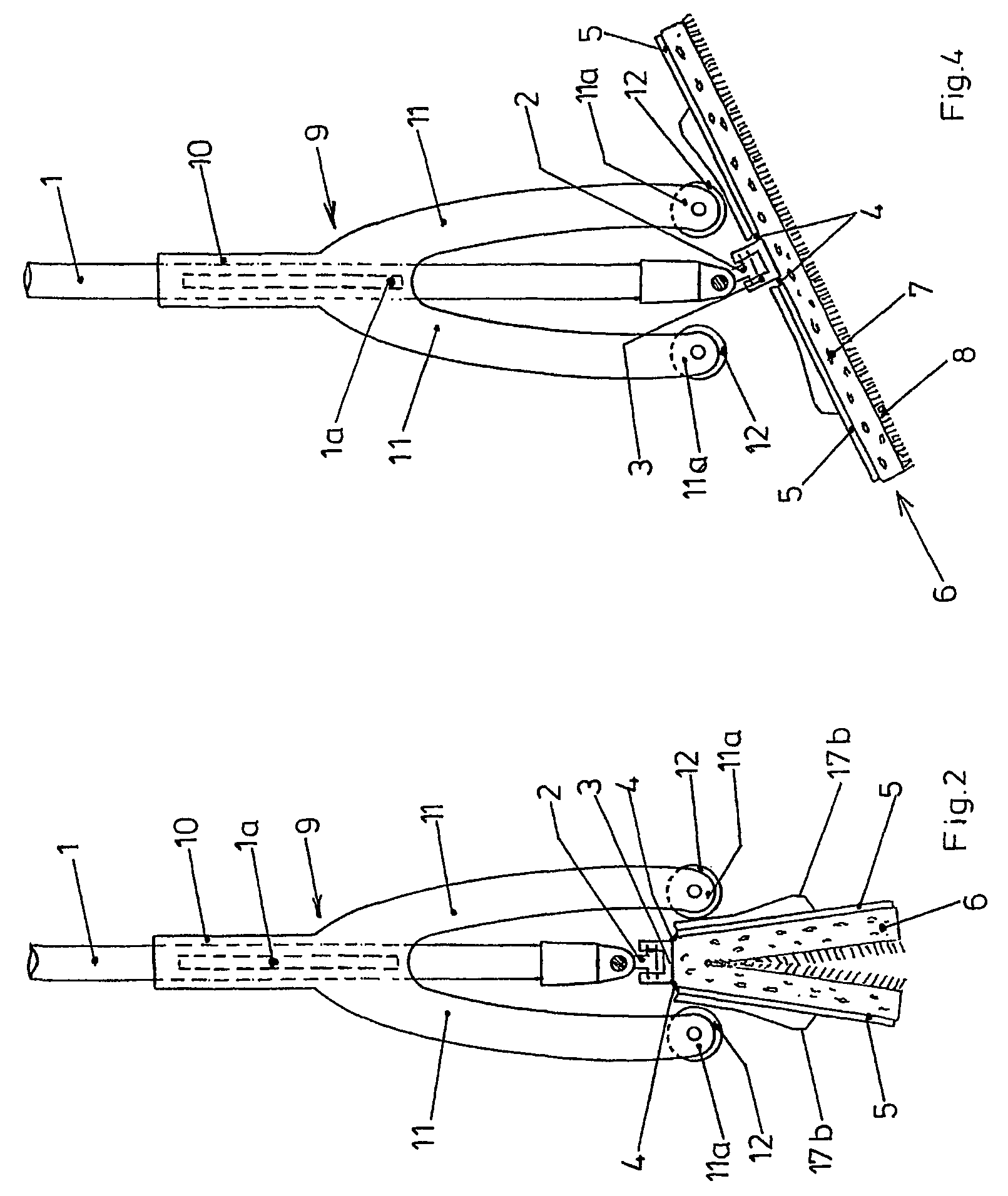
[0031]The floor mop shown in FIGS. 1-5 has a mop handle 1 which is connected via a Cardan joint 2 to a supporting centerpiece 3 non-rotatably but pivotally in all directions. The supporting centerpiece 3 is connected via hinges 4 attached on both sides to a mop supporting wing 5.

[0032]The two mop supporting wings 5 and the supporting centerpiece 3 carry an absorbent, squeezable mop layer 6 which in the conventional fashion consists of a sponge layer 7 and a gauze coating 8.

[0033]A squeezing slider 9 is displaceable along the mop handle 1. The squeezing slider 9 has a guide sleeve 10 which is guided non-rotatably, longitudinally displaceably along the mop handle 1. For example, in the hole of the sleeve 10 there is provided a longitudinal groove into which a pin 1 a attached to the mop handle 1 engages.

[0034]The sleeve 10 is rigidly connected to two squeezing arms 11 which each carry a rotatably supported roller 12 as rotatable rollers at their ends 11a in the exemplary embodiment sh...


PUM

PropertyMeasurementUnit
circumferenceaaaaaaaaaa
convex pressureaaaaaaaaaa
widthaaaaaaaaaa

Abstract

A floor mop has two mop supporting wings, which carry an absorbent mop layer and are hinge-connected to a common supporting centerpiece. A mop handle is hinge-mounted to the supporting centerpiece via a Cardan joint. A squeezing slider, which is displaceable along the mop handle and is guided non-rotatably, has two rigid squeezing arms whose ends can each be brought into engagement with a guide surface on the upper side of the respectively assigned mop supporting wings via rollers. Each mop supporting wing forms a rectangular trapezium or triangle. The edges running at right angles to the hinge edge of each mop supporting wing form a common straight continuous front edge.

Description

BACKGROUND[0001]The invention relates to a floor mop comprising two mop supporting wings which carry an absorbent mop layer and are hinge-connected to a mop handle and comprising a squeezing slider which is displaceable along the mop handle and has two rigid squeezing arms whose ends can each be brought into engagement with a guide surface on the back side of the respectively assigned mop supporting wings.[0002]Floor mops comprising two mop supporting wings which can be hinged towards one another to squeeze out the mop layer, also known as a butterfly floor mop, are known in various designs. In the floor mops according to U.S. Pat. No. 5,483,720 and International Patent Application PCT / US95 / 10759, a sleeve displaceable along the mop handle is connected via a guide rod to two clamps pivotally supported on the supporting centerpiece, which on displacement of the sleeve, slide along on the back side of the two mop supporting wings and thereby press these together. In this case, the mop...

Claims


Application Information

Patent Timeline
Patent Type & Authority Patents(United States)
IPC IPC(8): A47L13/146
CPCA47L13/146A47L13/258
Inventor HIRSE, GERNOT
Owner CARL FREUDENBERG KG
Why Eureka
Try Eureka