

Masonry anchoring system
a technology of anchoring system and masonry, which is applied in the direction of walls, foundation engineering, ceilings, etc., can solve the problems of time-consuming and expensive installation of the system, many masonry veneers do not have the structural integrity to accommodate, and many masonry veneers do not have the necessary structural integrity to accommoda
- Summary
- Abstract
- Description
- Claims
- Application Information
AI Technical Summary
Benefits of technology
Problems solved by technology
Method used
Image

Examples
Embodiment Construction
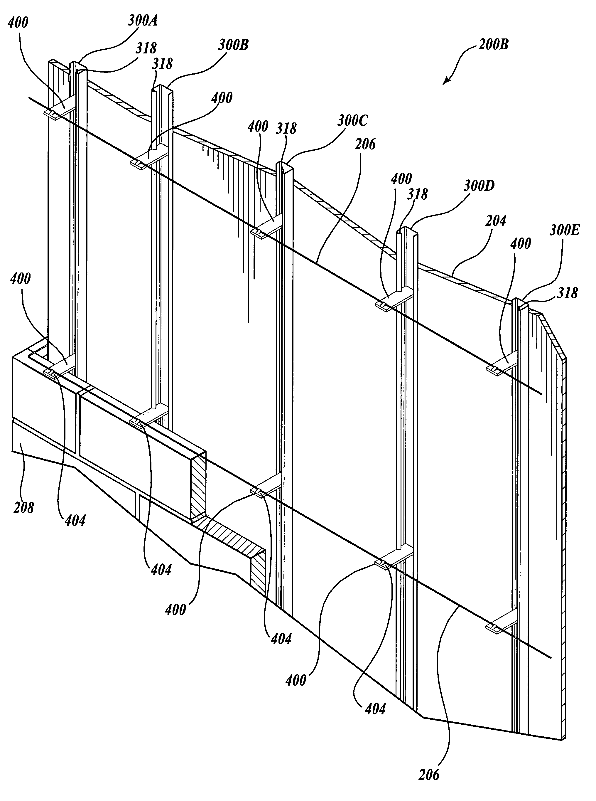
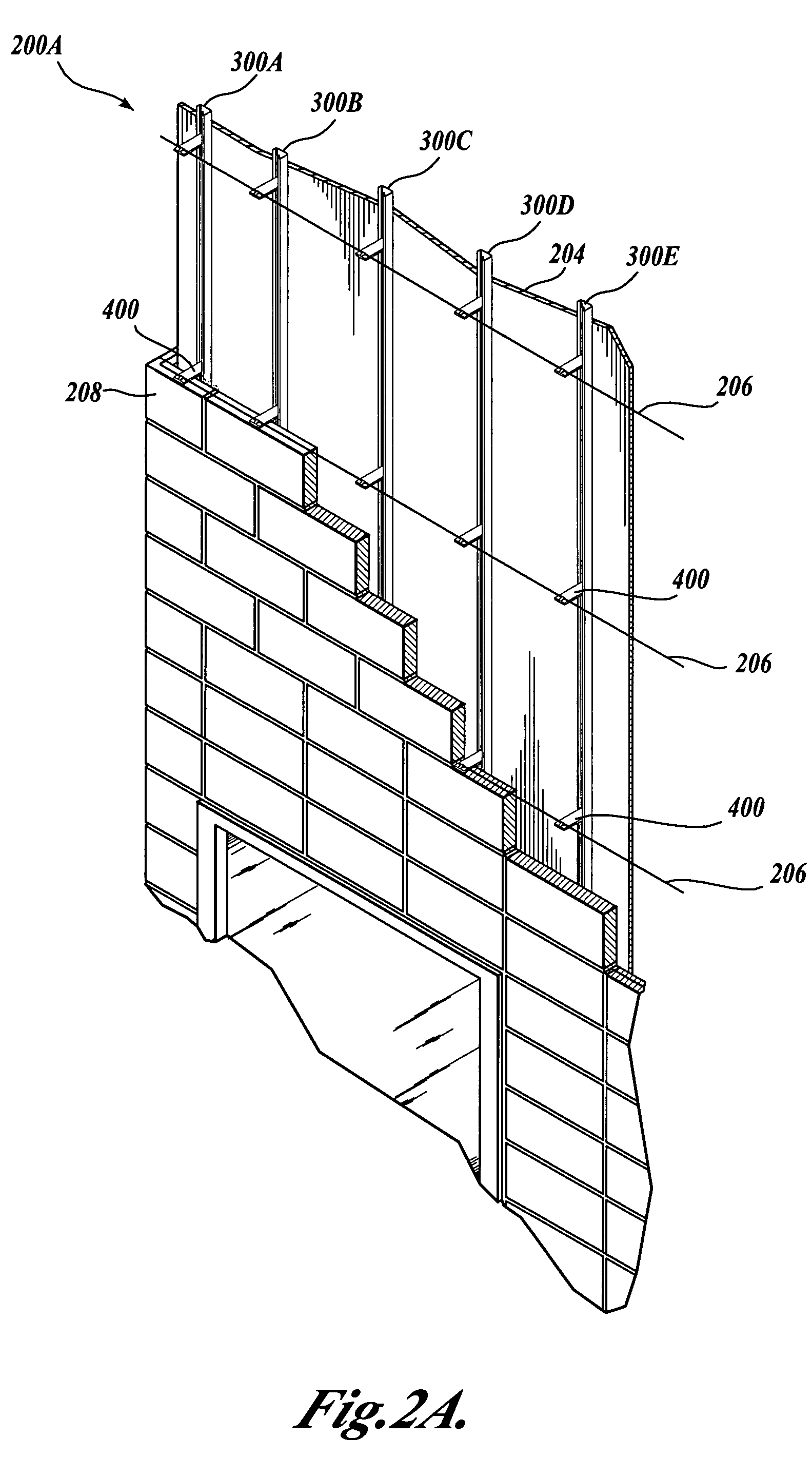
[0024]Generally described, the present invention provides a system and device for anchoring masonry veneer to a structure, such as, for example, an interior wall or exterior wall of a building (commercial or residential). Masonry veneers are a popular construction design for commercial buildings. Various embodiments of the present invention provides a coupling system to securely anchor a masonry veneer to structural walls that complies with commercial building codes. Preferably, the coupling system eases the toilsome effort with which a mason installs masonry veneers. Various embodiments of the invention inhibit moisture intrusion through the coupling system. In various embodiments, an anchor, which extends longitudinally, is mounted on a wall of a structure. A number of keys that interface the masonry veneer interlock with the anchor mounted on the wall of the structure.
[0025]The shape of the anchor and key provide several unexpected advantages over other anchoring systems. For exa...
PUM
 Abstract
Description
Claims
Application Information