Flares including reactive foil for igniting a combustible grain thereof and methods of fabricating and igniting such flares

a technology of reactive foil and flares, which is applied in the field of pyrotechnic flares, can solve the problems of extremely dangerous flares, impulsive charge devices that may explode or cause explosions, and the ability to safely fabricate and use flares

Active Publication Date: 2008-12-30
NORTHROP GRUMMAN SYST CORP
View PDF87 Cites 18 Cited by
  • Summary
  • Abstract
  • Description
  • Claims
  • Application Information

AI Technical Summary

Problems solved by technology

Upon ignition, the impulse charge device may explode or cause an explosion.
Flares are extremely dangerous and the ability to safely fabricate and use flares is a constant challenge to those working in the art.
Furthermore, the incorporation of safety features or elements into flare designs has, in some cases, detrimentally affected the reliability of the decoys and caused an increase in the number of decoys that fail to properly and fully ignite.

Method used


Image

  • Flares including reactive foil for igniting a combustible grain thereof and methods of fabricating and igniting such flares
  • Flares including reactive foil for igniting a combustible grain thereof and methods of fabricating and igniting such flares
  • Flares including reactive foil for igniting a combustible grain thereof and methods of fabricating and igniting such flares

Examples


Embodiment Construction

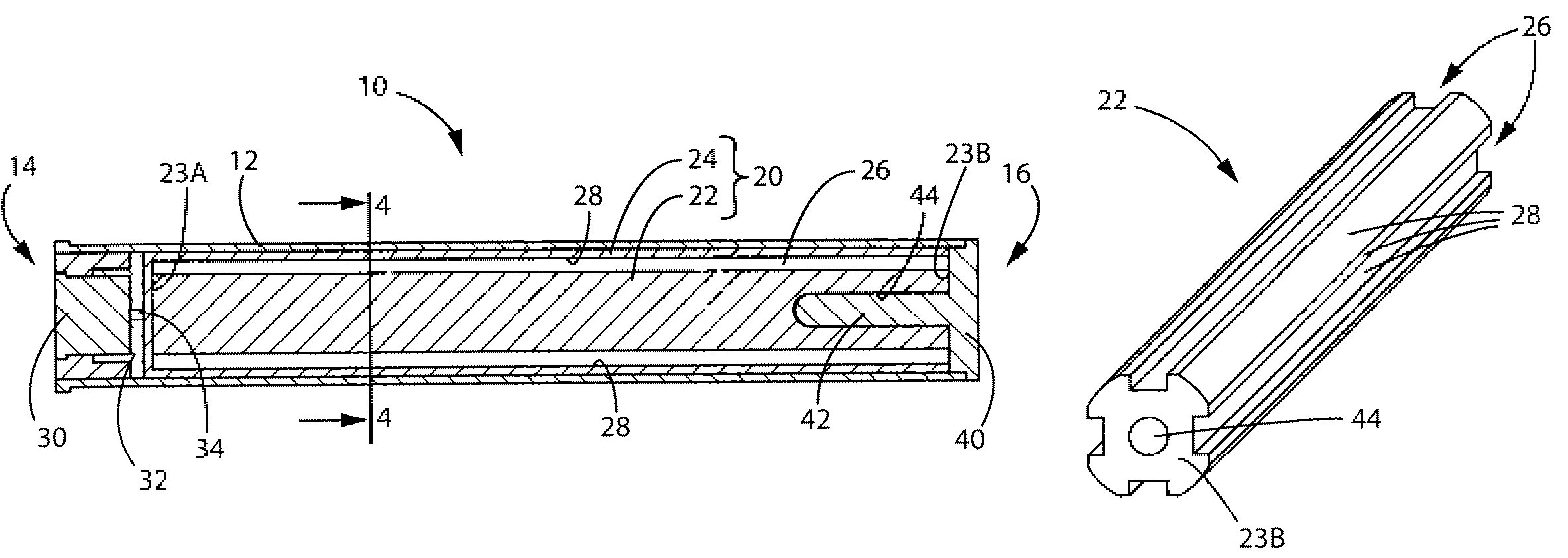
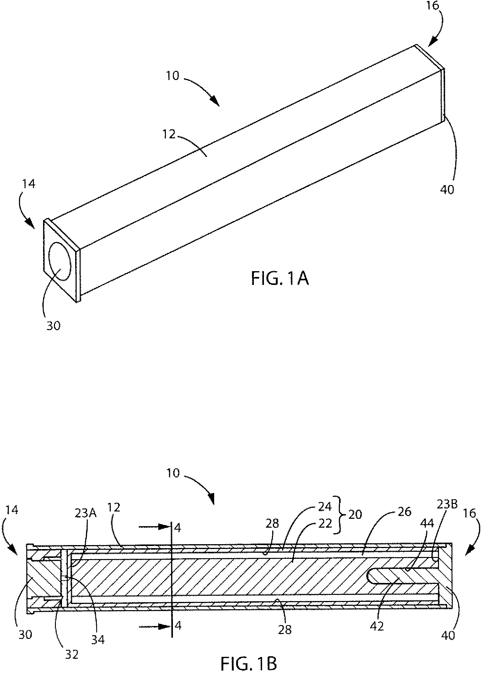
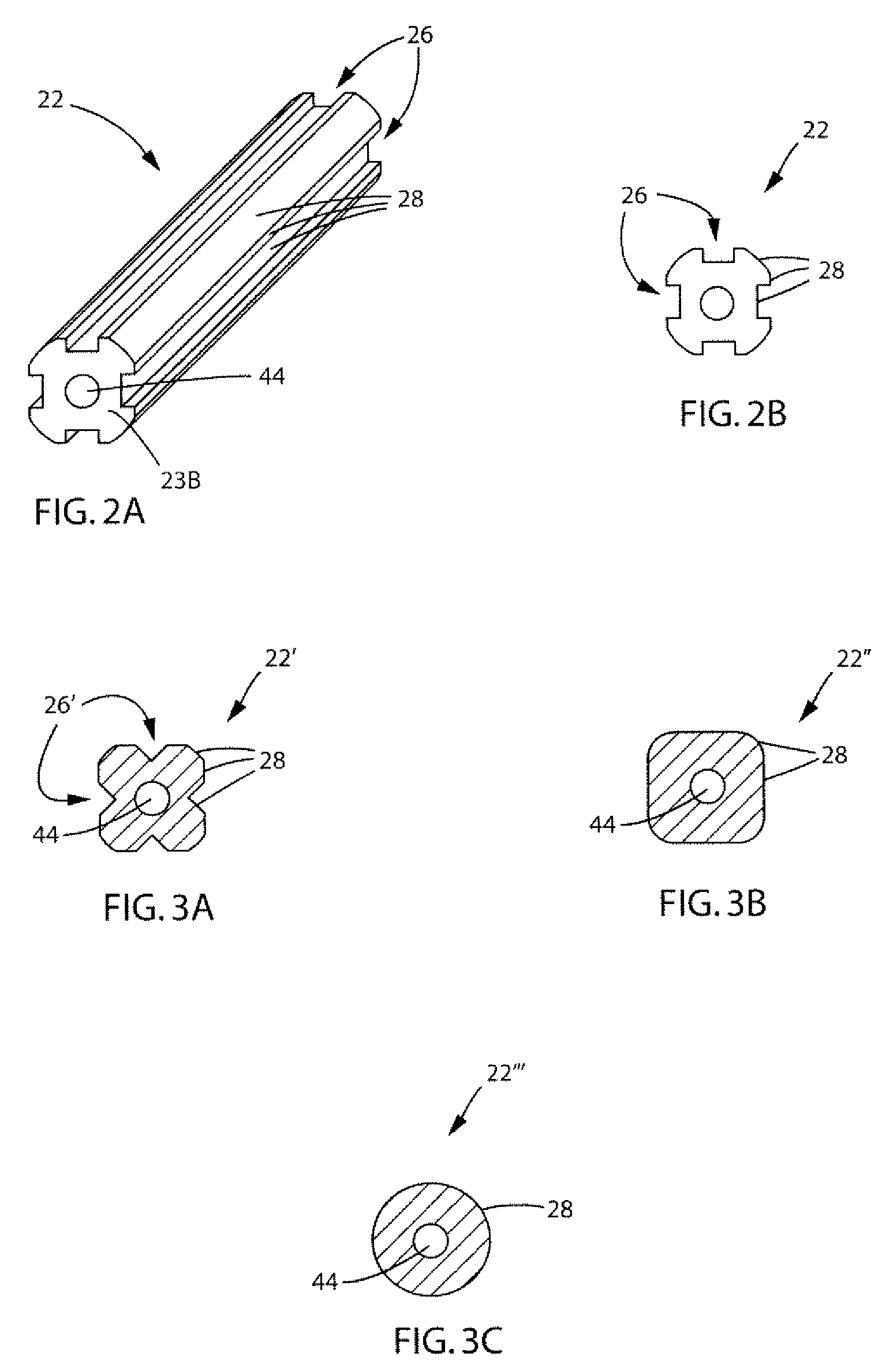
[0027]One example of a flare 10 that embodies teachings of the present invention is shown in FIGS. 1A-1B. The flare 10 includes a grain assembly 20 (FIG. 1B), which may be disposed within a casing 12. The grain assembly 20 includes a grain 22 of combustible material and a reactive foil 24 that is positioned relative to the grain 22 and configured to ignite combustion of the grain 22 upon ignition of the reactive foil 24. As will be discussed in further detail below, the reactive foil 24 may include alternating layers of different materials that are configured to react with one another in an exothermic chemical reaction upon ignition, which exothermic chemical reaction may be used to ignite combustion of the grain 22.

[0028]In some embodiments of the present invention, the flare 10 may be configured as a decoy flare, and the combustible material of the grain 22 may be configured to emit electromagnetic radiation (upon combustion of the grain 22) having a peak emission wavelength withi...


PUM

PropertyMeasurementUnit
thicknessaaaaaaaaaa
peak emission wavelengthaaaaaaaaaa

Abstract

Flares include grain assemblies comprising a combustible grain and a reactive foil positioned at least proximate to the grain and configured to ignite combustion of the grain upon ignition of the reactive foil. The reactive foil may include alternating layers of reactive materials. Methods of fabricating flares include at least partially covering an exterior surface of a combustible grain with a reactive foil to form a grain assembly, and inserting the grain assembly at least partially into a casing. The reactive foil may include alternating layers of reactive materials that are configured to react with one another in an exothermic chemical reaction upon ignition. Furthermore, methods of igniting a flare grain include initiating an exothermic chemical reaction between alternating layers of reactive materials in a reactive foil located proximate to the flare grain.

Description

FIELD OF THE INVENTION[0001]The present invention, in various embodiments, relates to pyrotechnic flares for use in signaling, illumination, defensive countermeasures, or a combination of several such functions. The present invention also relates to methods of fabricating and igniting such pyrotechnic flares.BACKGROUND OF THE INVENTION[0002]Flares are pyrotechnic devices designed to emit intense electromagnetic radiation at wavelengths in the visible region (i.e., light), the infrared region (i.e., heat), or both, of the electromagnetic radiation spectrum without exploding or producing an explosion. Conventionally, flares have been used for signaling, illumination, and defensive countermeasures in both civilian and military applications.[0003]Flares produce their electromagnetic radiation through the combustion of a primary pyrotechnic material that is conventionally referred to as the “grain” of the flare. The grain conventionally includes magnesium and fluoropolymer-based material...

Claims


Application Information

Patent Timeline
Patent Type & Authority Patents(United States)
IPC IPC(8): F42B4/26
CPCC06B45/12C06C15/00F42B4/26F42C19/0803F42B3/10Y10T29/49826
Inventor NIELSON, DANIEL B.TANNER, RICHARD L.DILG, CARL
Owner NORTHROP GRUMMAN SYST CORP
Why Eureka
Try Eureka