
Storage case

a storage case and disc support technology, applied in the field of storage cases, can solve the problems of large resistance, conventional example 1 is operationally problematic, and the disc support plate cannot push the disc upward to a sufficient height from the case body when the case cover is opened, etc., to achieve convenient inserting or taking out, high-quality storage cases, and smooth and efficient rotation

Inactive Publication Date: 2008-12-30
SONY CORP
View PDF13 Cites 4 Cited by
  • Summary
  • Abstract
  • Description
  • Claims
  • Application Information

AI Technical Summary

Benefits of technology

The present invention is a storage case with a holding segment for holding objects to be stored, a four-link mechanism for smoothly rotating the supporting plate between a storing position and a position at which the supporting plate is drawn out from the case body, and a fixed opened angle of the case cover and the supporting plate for stable attachment and detachment operations of the object to be stored. The technical effects of the invention are high-durability, high-quality storage case and stable attachment and detachment operations of the object to be stored.

Problems solved by technology

This means that a large resistance is present when the closing operation of the case cover is performed at the early stage of use.
For this reason, conventional example 1 is operationally problematic since a large force is required for opening the case cover at the early stage of use.
On the other hand, if the elasticity of the base end of the disc-supporting plate becomes deteriorated after a long usage, the disc-supporting plate cannot push the disc upward to a sufficient height from the case body when the case cover is opened.
Consequently, this structure is problematic in having low durability.
This structure of conventional example 2 is problematic in that a strong impulse is constantly applied to the first end of the supporting plate.
Consequently, since the first end of the supporting plate can be easily damaged, the conventional example 2 is problematic in having low durability, like the conventional example 1.
In this case, since a large thickness is required for the case body, a storage case having this structure is not suitable for storing bare discs.

Method used


Image

  • Storage case
  • Storage case
  • Storage case

Examples


first embodiment

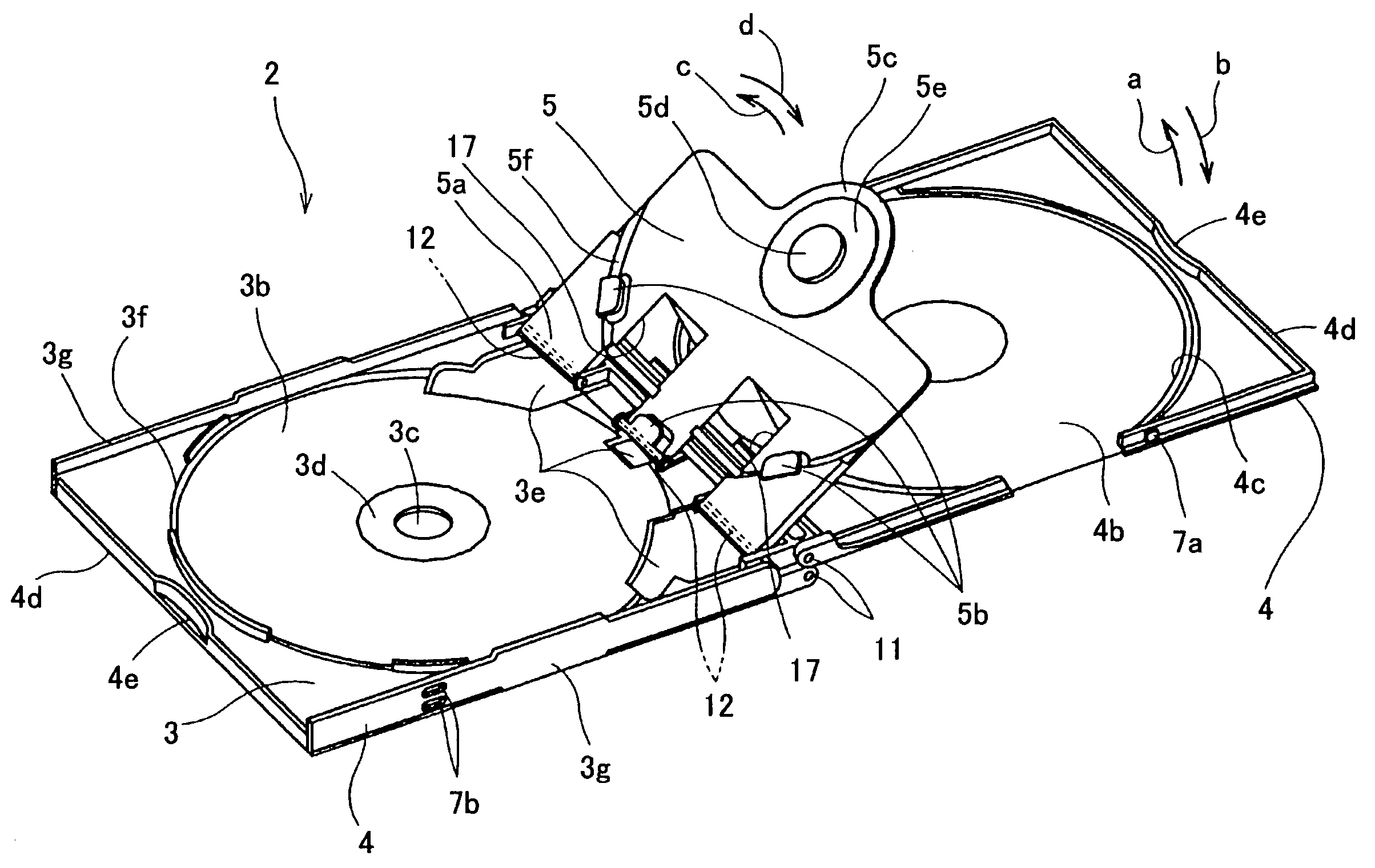
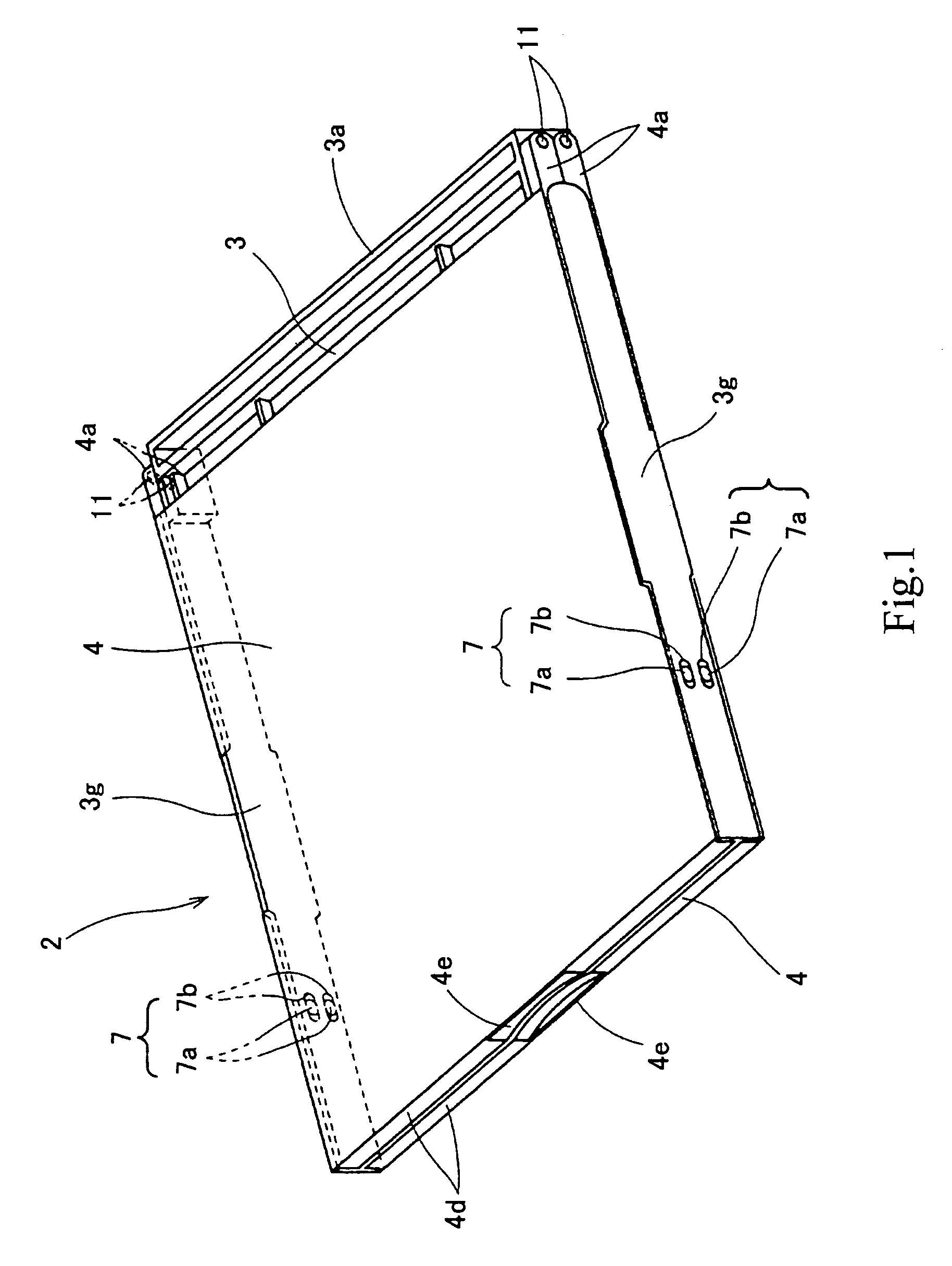
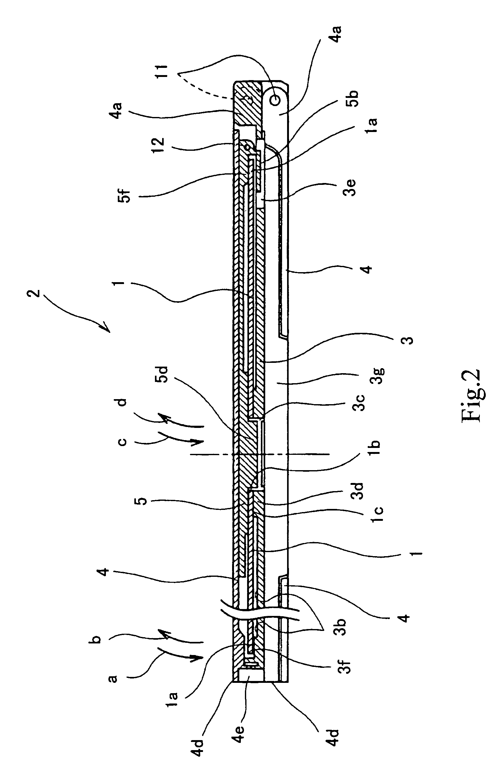
[0027]A storage case according to a first embodiment of the present invention will now be described with reference to the drawings. In the first embodiment, a storage case 2 is capable of storing bare 12-cm-diameter discs 1, which may be, for example, optical discs, magneto-optical discs, or magnetic discs. For example, each disc 1 may be a CD, a DVD, or a DVD-ROM. Alternatively, the storage case 2 can similarly store other types of bare discs having different diameters, such as 8-cm-diameter MO discs, by changing the dimension of the storage case 2.

[0028]The storage case 2 is composed of, for example, synthetic resin and includes two case covers 4 and two supporting plates 5 respectively attached to opposites sides of a case body 3, such that the storage case 2 is capable of storing two discs 1 on the opposites sides of the case body 3. Since the storage case 2 is symmetrical with respect to the case body 3, the structural description below will be directed to the relationships amo...


PUM

PropertyMeasurementUnit
heightaaaaaaaaaa
elasticityaaaaaaaaaa
angleaaaaaaaaaa

Abstract

A high-durability storage case is provided in which a disc can be smoothly inserted into and taken out from the storage case, and in which attachment and detachment operations of the disc can be stably performed. According to the storage case (2), a case body (3), a case cover (4), and a supporting plate (5) supporting a disc (1) are pivotally supported in a mutually openable / closeable manner by a four-link mechanism (16) defined by first, second, third, and fourth hinges (11), (12), (14), (15) and an arm segment (13). When the case cover (4) is opened or closed with respect to the case body (3), the supporting plate (5) is drawn into or drawn away from the case body (3) together with the case cover (4).

Description

TECHNICAL FIELD[0001]The present invention relates to storage cases suitable for storing recording media, such as bare discs, e.g., optical discs, magneto-optical discs, and magnetic discs, and cassettes, e.g., floppy disc cassettes and video tape cassettes, or for storing various types of objects similar to these recording media.BACKGROUND ART[0002]A conventional example 1 (Japanese Unexamined Patent Application Publication No. 2001-180780) discusses a storage case for storing a bare disc in which a base end of a disc-supporting plate is fixed to a case body. The disc-supporting plate is biased upward at an angle from the case body due to the elasticity of the base end. When a case cover is to be closed over the case body in a state where a disc is held at an angle by a disc-holding portion provided on an upper surface of the disc-supporting plate, the disc-supporting plate is pushed into the case body with the case cover against the elasticity of the base end, whereby the disc-sup...

Claims


Application Information

Patent Timeline
Patent Type & Authority Patents(United States)
IPC IPC(8): B65D85/30B65D85/57G11B23/023G11B23/03G11B33/04
CPCG11B33/045B65D85/544G11B23/023G11B23/03
Inventor MURATA, MORIHIROMATSUMURA, MITSUNORISUZUKI, IPPEI
Owner SONY CORP
Learn More