
Load transference in grinding disks

a technology of load transfer and grinding disk, which is applied in the direction of cocoa, stone-like material working tools, grain treatment, etc., can solve the problems of sudden resistance to disk rotation, catastrophic results for disk assembly and associated equipment, and exceptionally high strain on bolts, so as to facilitate and determine the degree of energy transmission, the effect of rapid assembling and maintaining

Inactive Publication Date: 2008-12-30
PROGRESSIVE IP
View PDF8 Cites 8 Cited by
  • Summary
  • Abstract
  • Description
  • Claims
  • Application Information

AI Technical Summary

Benefits of technology

[0048]said connection elements forming an adjustable connection which allows the retaining segments to be drawn towards the hub, the resulting interaction on their associated disk sections being to help secure the disk sections to the hub,
[0064]The provision of a retaining element acting in the aforesaid manner provides a vehicle for energy dispersion other than to key or critical components in the disk assembly. Here the attempt to move the retaining segments outwardly transmits energy to the connection elements connecting the retaining segments to the hub. These can be designed to be sacrificial, and their connection to the hub may be more robust (e.g. to a stronger part of the hub). In practice it may also be found that severe impacts may serve to slightly dislocate a disk section and adjacent sections—the retaining segment design can provide for this, as well as allowing the sections to be quickly adjusted and realigned. Again this is a form of energy absorption other than catastrophic failure of key components.
[0066]To achieve this effect of outward movement of the retaining segment, it is desirable that the contacting walls of the retaining segment which interact with the walls of removed portions of the associated disk sections (which accommodate the retaining segment), are not parallel to the radial reference plane. Ideally these should be curved, tapered, inclined, or otherwise featured such that the complementary width of the retaining segment at the bottom (i.e. the face closest to the centre of the disk assembly) is narrower than its topmost face. Ideally also, the contouring should be such that attempting to squeeze two adjacent disk sections together (if this were possible, though in practice there may be a slight gap introduced between adjacent disk sections in a disk assembly) had the effect of gently squeezing the retaining segment outwardly away from the centre of the disk assembly. Accordingly, contours which lock or hold the retaining segment in place (with respect to outwardly radial movement) should be avoided.
[0068]Accordingly, these long bolts, whose passage through the disk sections are accommodated by suitably removed portions in the disk sections and hub, retain the retaining segments, and consequently the individual disk sections in place. Additionally, if the left and right contacting faces of the retaining segment (when viewed from the front) are relatively symmetrical with respect to the radial reference plane, then tightening of the bolts will have an equivalent and self aligning effect on adjacent disk sections. This can provide some advantage in rapidly assembling and maintaining a disk assembly in a manner such that one achieves a substantially a true circle about its circumference.
[0069]In preferred embodiments some additional connection elements may be provided between a disk section and hub, ideally positioned near the bottom (first) face of the disk section, and ideally passing through overlapping portions of disk section and hub when a circumferential hub flange is present. These connections need not be overly strong or secure and may even permit a small degree of movement (within a plane substantially perpendicular to the rotational axis of the hub) between the disk section and hub. Normally this movement would be restrained by the retaining segments and their connection elements to the hub. This small degree of permitted movement can facilitate and determine the degree of energy transmission to a retaining segment and its associated connection elements, etc.
[0073]It is also considered that in severe cases of obstruction, individual teeth will likely break off, reducing the maximum load and impact which can be exerted in a localized manner on a single disk section. This can be taken into account in the specific design of a disk assembly according to the present invention.

Problems solved by technology

The problems encountered when acting on these different materials are largely similar, though some of the problems may be more prevalent when acting on different types of material.
A problem often arises when sudden resistance to rotation of the disk is encountered.
The cause of such ‘impact’ is typically the entry of foreign materials such metal and rocks into the system rather than the substantially softer wood which is being processed.
Such impacts place an exceptionally high strain on the bolts, generally positioned on the inner end of the segments and connecting them to the hub.
This can, in exceptional circumstances, lead to catastrophic failure of those bolts with potentially disastrous results for the disk assembly and associated equipment.
Fortunately, in well maintained equipment this is not common, though frequent maintenance is generally required, and the system is nevertheless occasionally exposed to significant stresses from such sharp impacts.
The likelihood of catastrophic failure is increased, and the need for regular preventative maintenance becomes even more pronounced.
Hence, what represented a problem for disks acting on wood, becomes a major problem for disks acting on harder materials.
Another problem which is often prevalent in grinding disks is the misalignment of disk sections, generally contributed to by repeated impacts.
However, over time, and as a consequence of impact, the arcuate outer edges of the sections can become misaligned, with steps resulting between adjacent sections.
In current designs there is no easy fine adjustment to allow for quick realignment of the disk sections, and fixing the problem may require machining of the connections with the hub.

Method used


Image

  • Load transference in grinding disks
  • Load transference in grinding disks
  • Load transference in grinding disks

Examples


Embodiment Construction

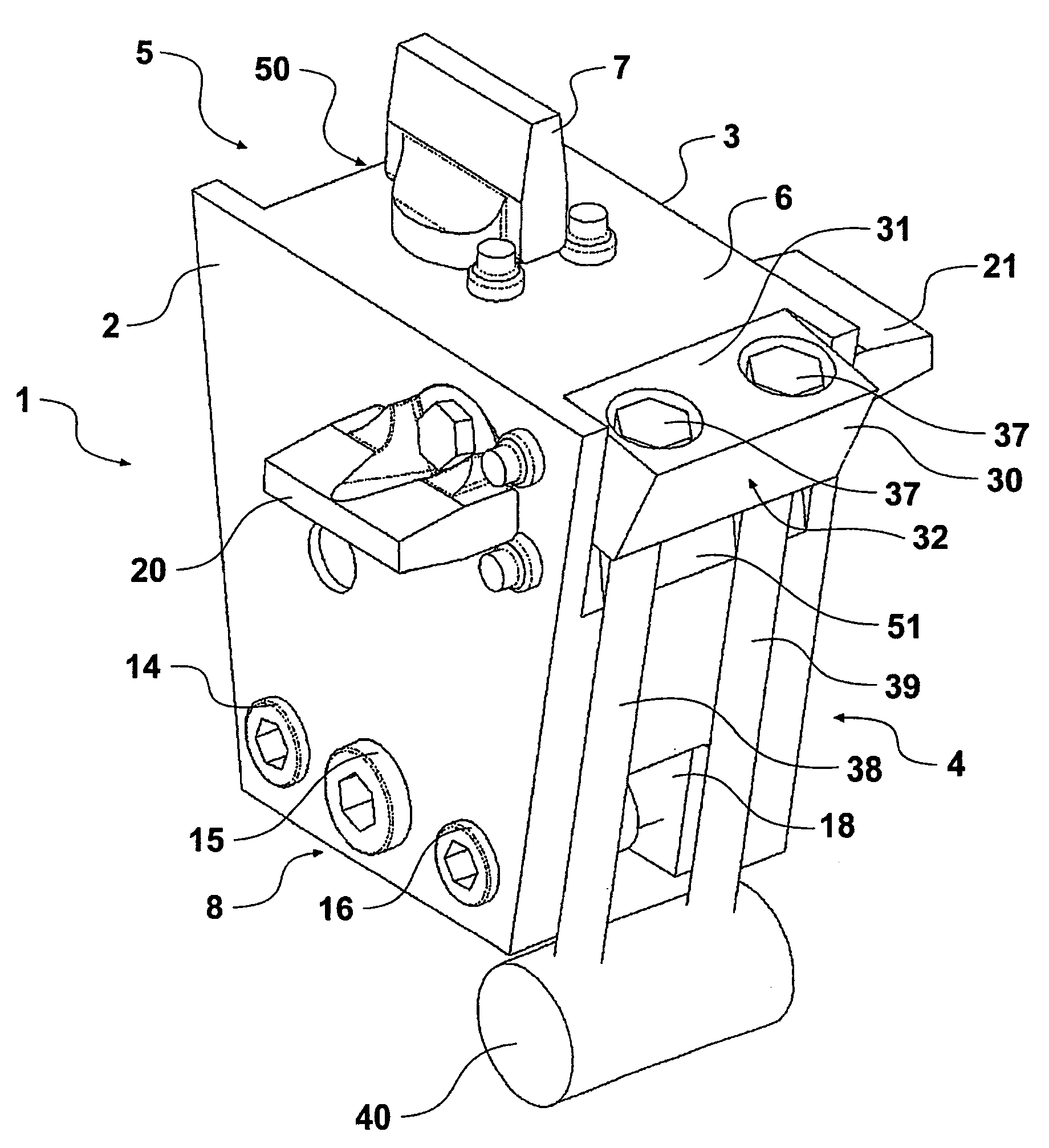
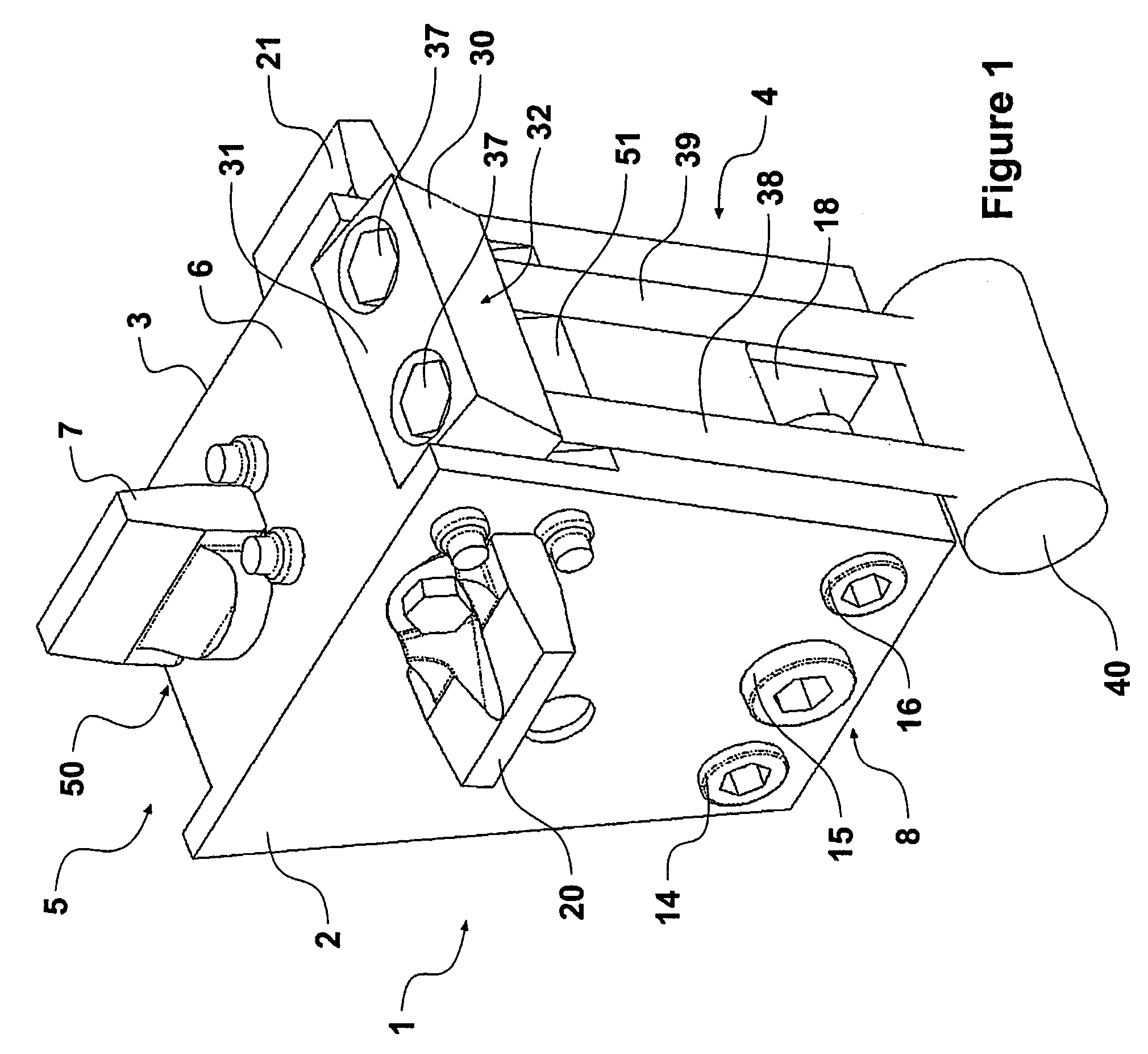
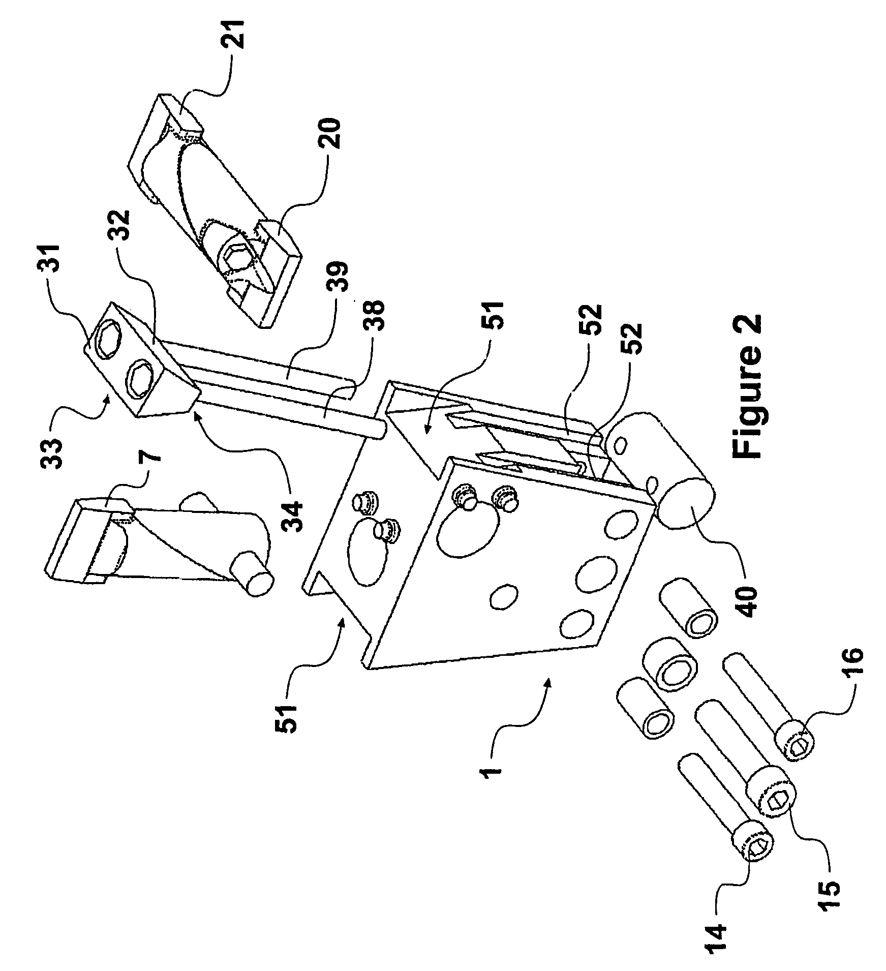
[0077]With reference to the drawings and by way of example only, there is shown in FIG. 1 a disk section, generally indicated by arrow 1. This has a front face (2), rear face (3), and end faces indicated by arrows 4 and 5. The top face is indicated by arrow 6 and includes a removable tooth assembly (7). The bottom most edge indicated by arrow 8, above the central hub (9) and the completed disk assembly (10).

[0078]Provided and visible near the bottom most edge of the front face (2) are apertures passing through the disk section (1) and which locate retaining bolts (14, 15, 16). These retaining bolts secure the disk section (2) to the disk hub (9).

[0079]It can also be seen in FIG. 1 that there is a removable portion (18) which accommodates an upward circumferential flange (not visible) on the hub (9). The locating bolts (14-16) pass through corresponding apertures in the flange. A sleeve may optionally be provided about the locating bolts (14-16) in this region.

[0080]The illustrated e...


PUM

PropertyMeasurementUnit
volumeaaaaaaaaaa
forceaaaaaaaaaa
resistanceaaaaaaaaaa

Abstract

The present invention relates to a disk section (1) for use in the construction of a grinding disk (10) such as may be used in wood hogging, chipping, or grinding apparatus. The disk section (1) is associated with a substantially wedge shaped retaining segment (30) which is positioned near the circumference of the assembled grinding disk(10), and preferentially overlaps at least part of two adjacent disk sections (1) thereon. The arrangement is such that tangential type impacts acting on a disk section (1) results in at least partial energy transmission to the retaining segment (30) and its connection (38, 39) to a hub (9).

Description

FIELD OF INVENTION[0001]The present invention is directed to methods of transferring loads encountered by localized resistance to rotation in disk assemblies. In particular such disk assemblies are commonly used in grinding, chipping, breaking, and crushing operations, and including in devices such as wood hoggers.BACKGROUND DESCRIPTION[0002]The present invention takes into account problems associated with grinding disks and such like in equipment such as wood hoggers. However, many such devices are being used to break down a variety of different materials including soft and hard rocks, recycled asphalt and roading, demolition masonry, and tires etc. The problems encountered when acting on these different materials are largely similar, though some of the problems may be more prevalent when acting on different types of material. For simplicity of description, problems associated with wood hoggers comminuting wood materials will be referred to for the main part, though the teachings a...

Claims


Application Information

Patent Timeline
Patent Type & Authority Patents(United States)
IPC IPC(8): B02C1/08B02C13/20B02C7/04B02C1/00B02C7/12B02C18/18B27L11/00B28D1/18
CPCB02C18/18B28D1/188
Inventor SHARP, RODNEY WARWICK
Owner PROGRESSIVE IP
Learn More