Connecting structure of electric wire and electronic-component incorporating unit

a technology of connecting structure and electric wire, which is applied in the direction of connection contact material, contact member penetrating/cutting insulation/cable strand, coupling device connection, etc., can solve the problems of short strength of the portion relative to the electric connection, shortening of the crimped portion, and occurrence of malfunction, so as to improve the operation and prevent the damage of the electric-wire side terminal and the first connecting portion. , the effect of preventing the damage of the electric-

Inactive Publication Date: 2008-12-30
YAZAKI CORP
View PDF9 Cites 11 Cited by
  • Summary
  • Abstract
  • Description
  • Claims
  • Application Information

AI Technical Summary

Benefits of technology

[0009]This invention has been accomplished in view of the above circumstance. An object of this invention is to provide a connecting structure of an electric wire and an electronic-component incorporating unit, which can improve the operability and also prevent catching of the electric wire and damaging of an electric wire side terminal.

Problems solved by technology

This leads to a problem of occurrence of malfunction.
Meanwhile, the noise preventing tool according to the related art has a problem that if external force is applied to the electric wire, the crimped portion will come off.
Namely, the noise preventing tool has a problem that the portion relative to electric connection is short of strength.
However, since this connecting structure is a structure in which the covers and electric wire are assembled separately, it has problems of poor operability, and fears of occurrence of catching of the electric wire and occurrence of damaging / curving of the electric-wire side terminal.

Method used


Image

  • Connecting structure of electric wire and electronic-component incorporating unit
  • Connecting structure of electric wire and electronic-component incorporating unit
  • Connecting structure of electric wire and electronic-component incorporating unit

Examples


Embodiment Construction

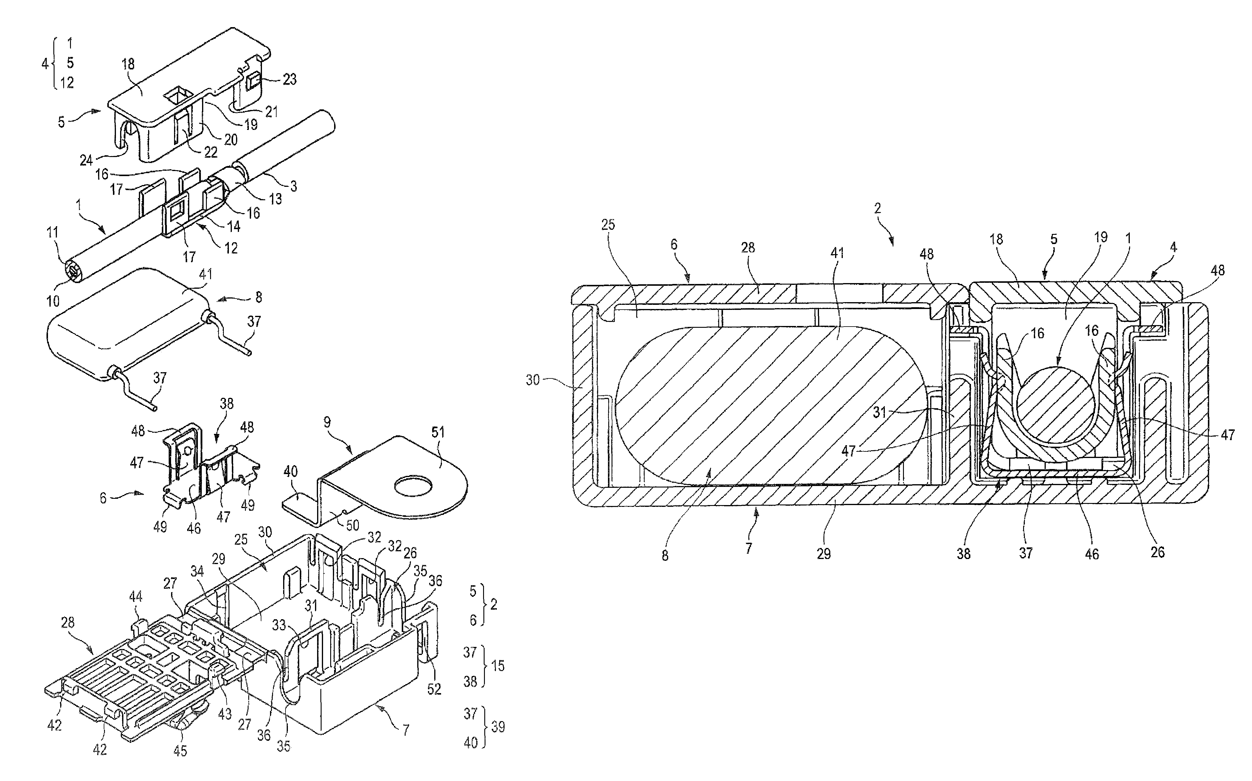
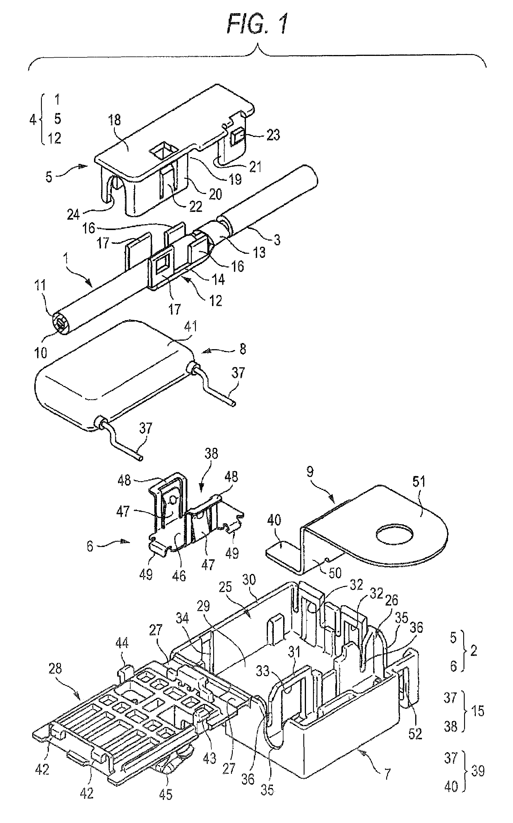
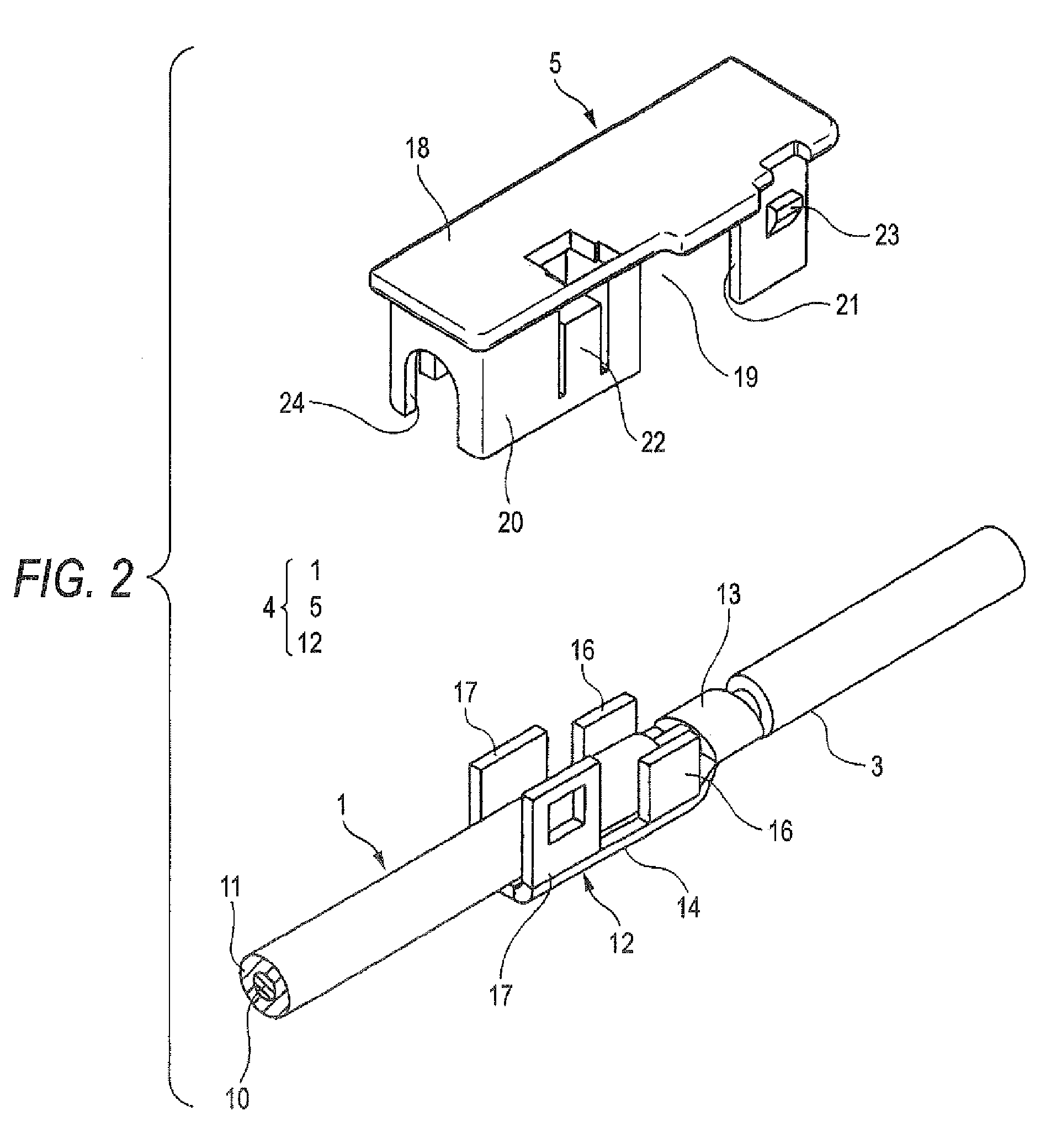
[0046]Now referring to the drawings, an explanation will be given of the invention. FIG. 1 is an exploded perspective view of an embodiment of the connecting structure between an electric wire and an electronic-component incorporating unit according to this invention. FIG. 2 is an exploded perspective view of a cover-assembled wire. FIG. 3A is a perspective view of a unit body. FIG. 3B is an enlarged perspective view of a spring contact in FIG. 3A. FIG. 4 is a perspective view showing the state where the electronic-component incorporating unit is attached to the middle of the electric wire. FIG. 5 is a sectional view taken in line A-A in FIG. 4. FIG. 6 is a perspective view of a relay terminal constituting a first connecting portion. FIG. 7 is a view showing the state where a cover member is to be fit in a direction which is not normal. FIG. 8 is a view showing the state where the side wall of the cover member is brought into contact with fitting-limiting parts from the state in FIG...


PUM


Abstract

A connecting structure includes a unit body including a case having an electronic-component housing concave portion and a fitting-connection concave portion and an electronic component housed in the electronic-component housing concave portion and making a first connecting portion in the fitting-connection concave portion; an electric wire having an electric-wire side terminal in the middle of the electric wire in an electric-wire direction; and a cover member having an electric wire housing portion held on the electric wire so as to overlie an area of the electric-wire side terminal and a cover side fitting part to be fitted in the fitting-connection concave portion. In such a configuration, after the cover member is previously assembled with the electric wire to form a cover-assembled wire, the cover-assembled wire is fit in the fitting-connection concave portion and simultaneously therewith the first connecting portion is connected to the electric wire side terminal.

Description

BACKGROUND OF THE INVENTION[0001]1. Field of the Invention[0002]This invention relates to a connecting structure of an electric wire and an electronic-component incorporating unit incorporating an electronic component.[0003]2. Related Art[0004]As the case may be, various sensors mounted in e.g. a motor vehicle are supplied, through an electric wire, with noise conducted from a noise source having a high frequency component such as a phone or wiper motor, external noise from a neon sign or induction noise. This leads to a problem of occurrence of malfunction. Conventionally, in order to eliminate these noises, it has been proposed that a noise preventing tool or element incorporating unit as disclosed in the following JP-A-2-295199 and JP-A-2006-109587 is provided in the middle of the electric wire.[0005]The technique disclosed in the following JP-A-2-295199 is the noise preventing tool. This noise preventing tool is provided with an upper resin cover and a lower resin cover which ac...

Claims


Application Information

Patent Timeline
Patent Type & Authority Patents(United States)
IPC IPC(8): H01R9/03
CPCH01R4/185H01R4/64H01R13/6608H01R13/501H01R2201/26
Inventor YAMAGUCHI, TORUHONMA, HIDEKIKUROSAWA, TORU
Owner YAZAKI CORP
Why Eureka
Try Eureka