Needle with sealing valve

a technology of sealing valve and needle, which is applied in the direction of catheters, guide wires, other medical devices, etc., can solve the problems of exposing certain veins or other body cavities to atmospheric pressure, and reducing the service life of the needl

Active Publication Date: 2008-12-30
MEDICAL COMPONENTS INC
View PDF36 Cites 163 Cited by
  • Summary
  • Abstract
  • Description
  • Claims
  • Application Information

AI Technical Summary

Problems solved by technology

This is often troublesome, especially when aspirating blood vessels, due to the flashback of blood.
Arterial blood may spurt from the needle insertion point with considerable force and may contact a physician or other attendant assisting the physician, causing the risk of contamination with blood borne pathogens, such as HIV virus or hepatitis.
A second problem, which is of greater concern to the patient, is exposing certain venous blood vessels or other body cavities to atmospheric pressure.
Veins are often under negative pressure as blood is being drawn back to the thoracic cavity due to the process of inspiration during the breathing cycle, and a hole in a venous blood vessel could lead to air being drawn into the blood vessel, creating an air embolism.
The introduction of air into the thoracic cavity could cause the lungs to partially collapse.
However, the valve disclosed in this patent requires arterial blood pressure to close the valve.

Method used


Image

  • Needle with sealing valve
  • Needle with sealing valve
  • Needle with sealing valve

Examples


Embodiment Construction

[0020]In the drawings, like numerals indicate like elements throughout. The terms “distal” and “proximal” refer to the insertion end and the connecting end, respectively, of the needle assembly according to the present invention. The terminology includes the words above specifically mentioned, derivatives thereof and words of similar import. The embodiments illustrated below are not intended to be exhaustive or to limit the invention to the precise form disclosed. These embodiments are chosen and described to best explain the principle of the invention and its application and practical use and to enable others skilled in the art to best utilize the invention.

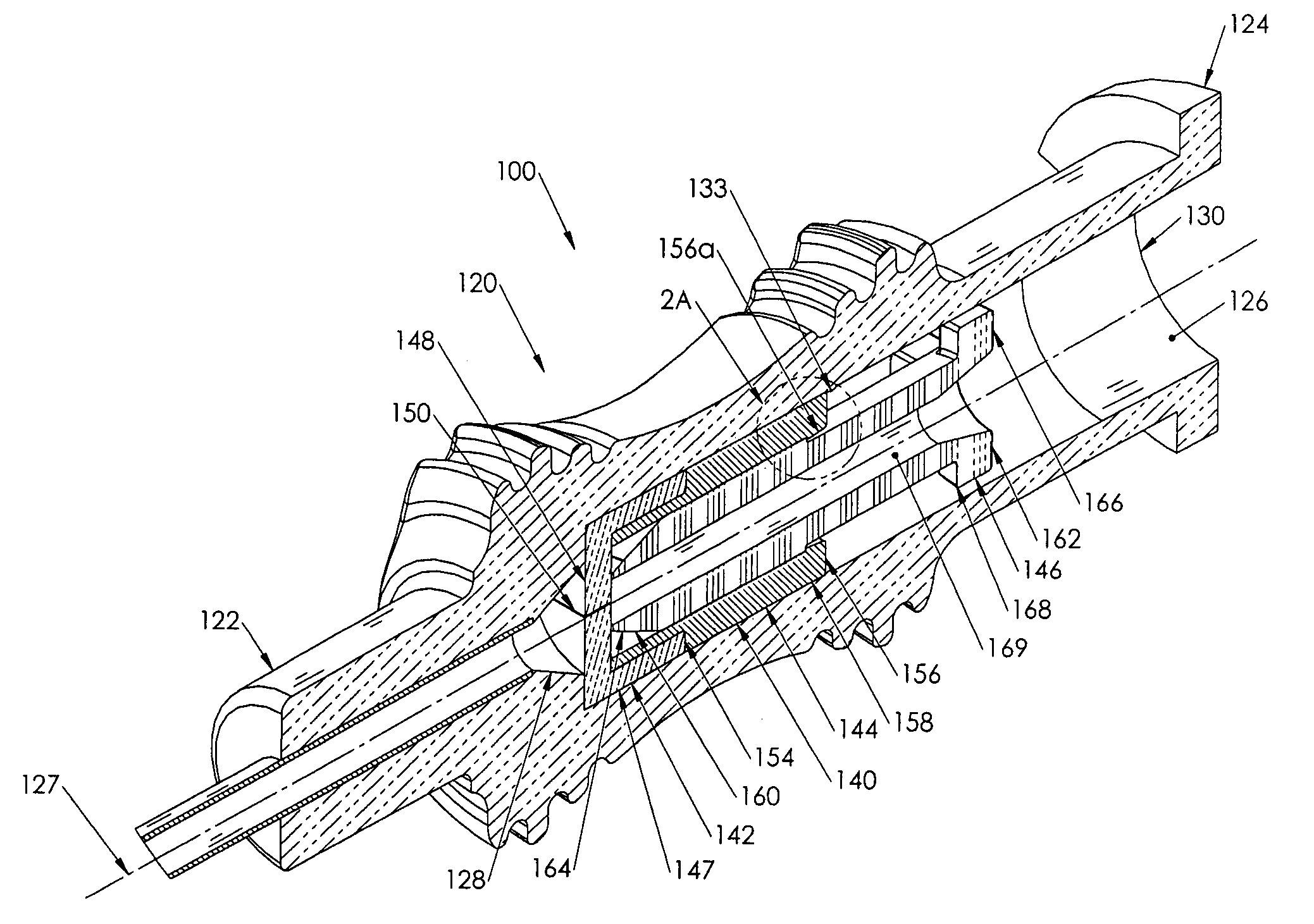
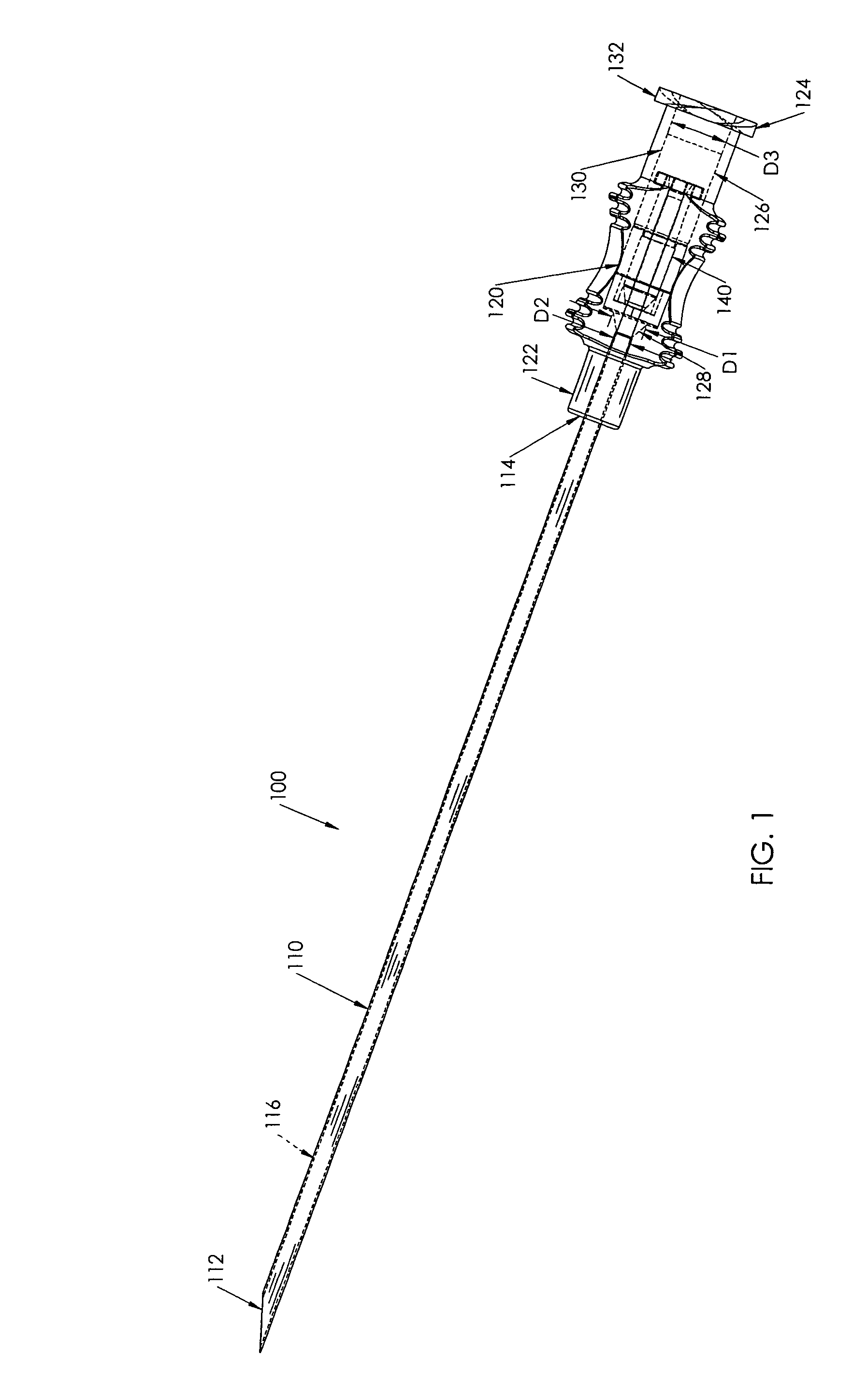
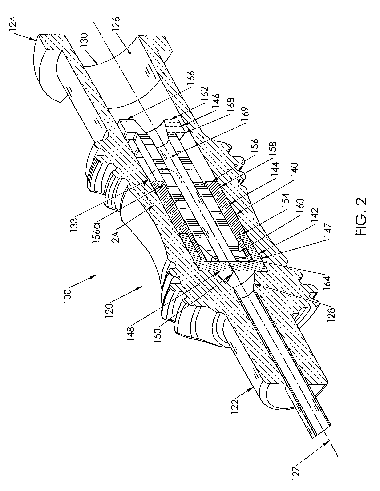
[0021]Referring now to FIG. 1, a catheter insertion needle assembly 100 according to the present invention is shown. The needle assembly 100 includes a needle 110 having a beveled distal tip 112 and a proximal end 114. The needle 110 includes a hollow cannulating portion 116 that extends between the distal tip 112 and the proxim...


PUM


Abstract

A needle assembly (100) having a hollow needle (110) with a pointed distal end (112) and a proximal end (114). The assembly also includes a needle hub (120) having a distal hub end (122) fixedly connected to the needle (110), a proximal hub end (124) having an opening, and a passageway (126) extending therethrough between the distal end and the proximal end. A valve (140) is disposed within the passageway (126), wherein the valve comprises a sealing member (142) having at least one through-opening (150) disposed therein and a plunger (146) disposed proximate the sealing member (142) and slidable between a first position wherein the at least one through-opening (150) is closed such that the hollow needle (110) and the proximal hub end (124) are not in fluid communication with each other and a second position wherein the plunger (146) biases the at least one through-opening (150) to an open position, such that the hollow needle and the proximal hub end are in fluid communication with each other. A method of using the needle assembly (100) is also disclosed.

Description

CROSS-REFERENCE TO RELATED APPLICATION[0001]The present application claims priority from U.S. Provisional Patent Application Ser. No. 60 / 495,988, filed on 18 Aug. 2003.FIELD OF THE INVENTION[0002]The present invention relates to a catheter insertion needle having a valve incorporated into the needle hub.BACKGROUND OF THE INVENTION[0003]Catheters for the introduction or removal of fluids may be located in various venous locations and cavities throughout the body for introducing or removing fluids. Such catheterization may be performed by using a single catheter having multiple lumens. A typical example of a multiple lumen catheter is a dual lumen catheter in which one lumen introduces fluids and one lumen removes fluids. Catheterization may also be performed by using separate, single lumen catheters inserted through two different incisions into an area to be catheterized. Such multiple catheter assemblies are known as TESIO® catheters sold by Medical Components, Inc. of Harleysville,...

Claims


Application Information

Patent Timeline
Patent Type & Authority Patents(United States)
IPC IPC(8): A61M5/178A61M25/01A61M25/06A61M25/09A61M39/06A61M39/26
CPCA61M25/01A61M25/09041A61M39/26A61M5/3293A61M25/065A61M25/0693A61M39/0606A61M39/0693
Inventor BASTA, MICHAELSANFORD, KEVINVOORHEES, JR., EARL W.
Owner MEDICAL COMPONENTS INC
Why Eureka
Try Eureka