Electromagnetic wave absorber

a technology of electromagnetic absorbers and absorbers, applied in the direction of magnetic/electric field screening, electrical equipment, antennas, etc., can solve the problem of long absorbers, and achieve the effect of reducing weight and cos

Active Publication Date: 2008-12-30
TDK CORPARATION
View PDF49 Cites 12 Cited by
  • Summary
  • Abstract
  • Description
  • Claims
  • Application Information

AI Technical Summary

Benefits of technology

[0016]Under such circumstance, a first object of the invention is to provide an electromagnetic wave absorber that can decrease weight and cost.
[0017]Another object of the invention is to provide an electromagnetic wave absorber that can obtain prefer absorption characteristic of electromagnetic waves in low-frequency as well as high-frequency with a short length, and cause no difference in the characteristic by a polarization plane of an arrival electromagnetic wave.

Problems solved by technology

By the way, the hollow wedge structure and the wedge structure composed of fitting two boards each other have a problem that a difference in the characteristic is caused by a polarization plane of an arrival electromagnetic wave.
A case of the wedge structure composed of fitting two boards each other, there is another problem in strength that each board cause sag or the like when a length of the boards is long.
But, there is a problem that the absorber must be made long, because the low-frequency characteristic of 30-100 MHz was inferior in comparison with the hollow wedge structure.

Method used


Image

  • Electromagnetic wave absorber
  • Electromagnetic wave absorber
  • Electromagnetic wave absorber

Examples


first embodiment

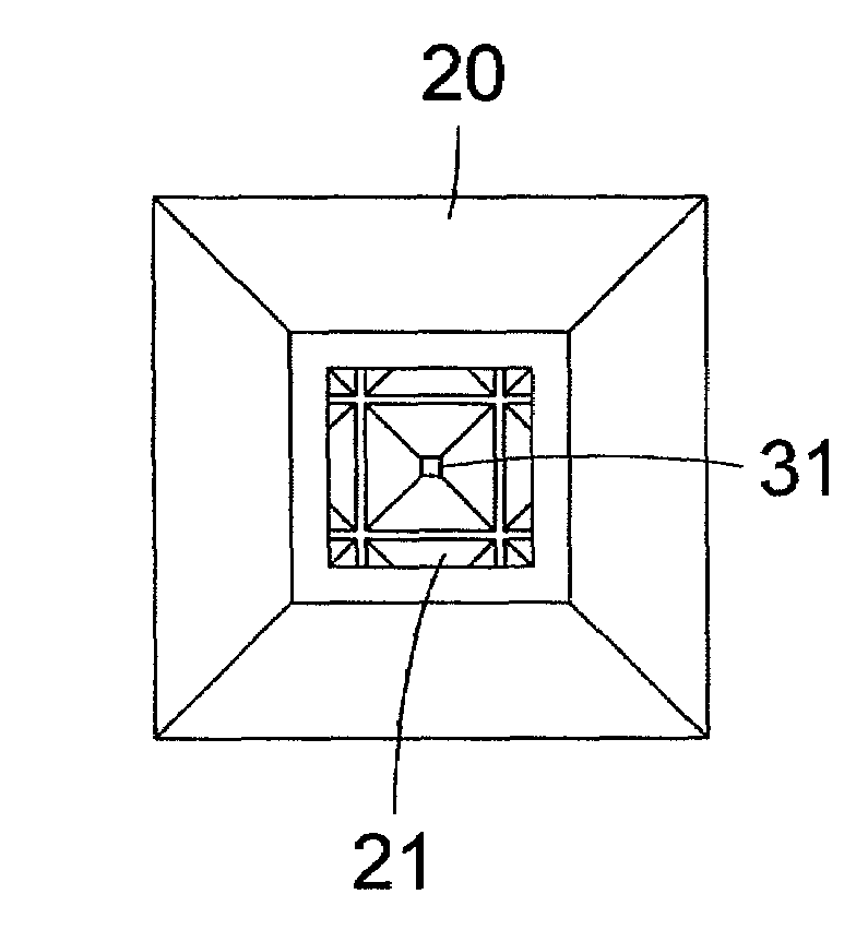
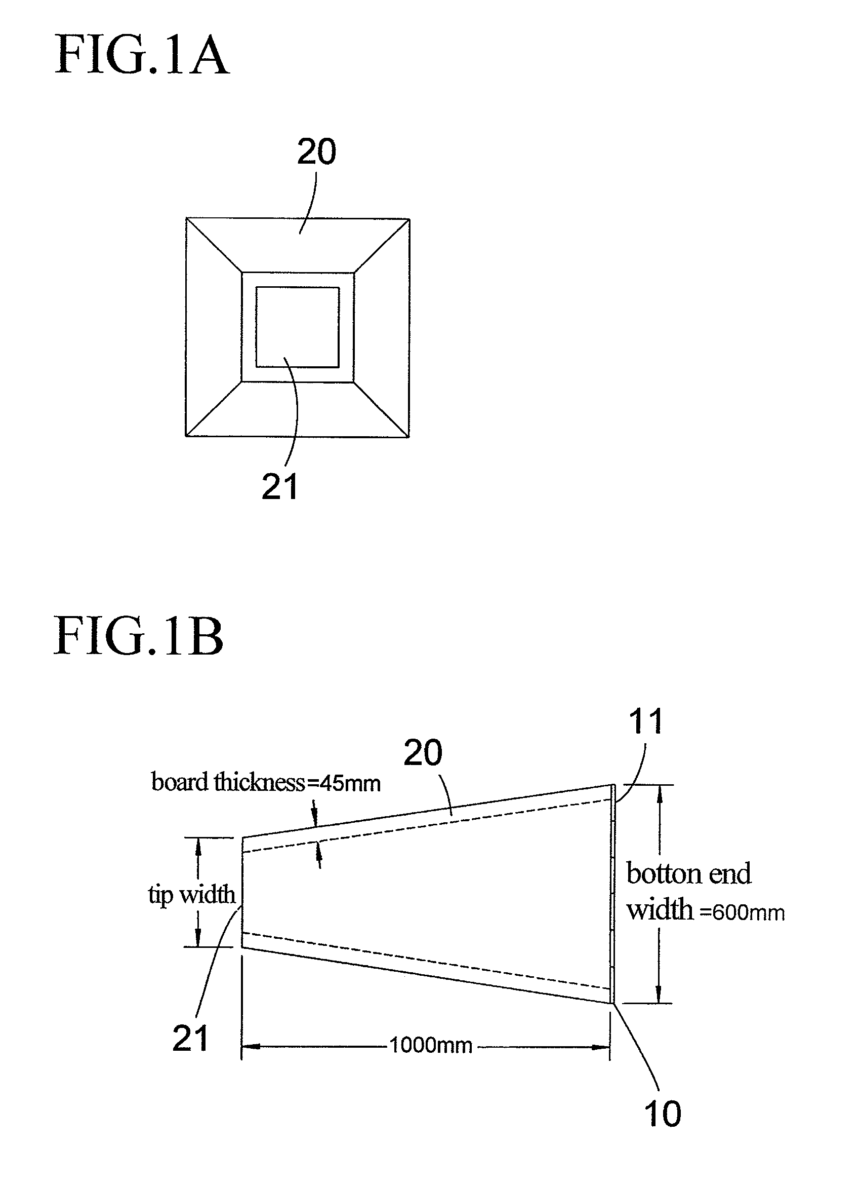
[0060]an electromagnetic wave absorber of the invention is explained according to FIGS. 1A, 1B-FIG. 3. As shown in FIGS. 1A, 1B, the electromagnetic wave absorber comprises a flat plate-shaped electromagnetic wave absorbent member 10 (a first electromagnetic wave absorbent member) which is made by spreading plate-shaped ferrite sintered compacts 11 as a magnetic loss material without gap so as to compose a flat plate-shaped wall body, and an electromagnetic wave absorbent member 20 (a second electromagnetic wave absorbent member) containing a conducting material which is arranged to front of the flat plate-shaped electromagnetic wave absorbent member 10. The electromagnetic wave absorbent member 20 has a shape that is formed an aperture 21 at the tip of a hollow cone. The electromagnetic wave absorbent member 20 is glued in front of the flat plate-shaped electromagnetic wave absorbent member 10 with, for example, adhesive or the like. In case of the drawings, the electromagnetic wav...

second embodiment

[0074]A second embodiment is explained according to FIGS. 4A, 4B. As shown in the figures, the electromagnetic wave absorbent member 20 containing the conducting material has the shape that the aperture 21 is formed at the tip of the hollow square cone, and more, has a jagged shape 22 at the edge of the surroundings of the aperture 21. The jagged shape 22 is composed of series of little tapered shapes (near cone shape or near mountain shape) or the like.

[0075]In this case, the jagged shape 22 formed at the tip of the electromagnetic wave absorbent member 20 has an effect of suppressing reflections in the high frequency of the use frequency range such as an electromagnetic wave anechoic room or the like. Other composition, action and effect are substantially the same as the first embodiment mentioned above, so the explanations are omitted by putting the same signs at the same or common parts.

third embodiment

[0076]A third embodiment is explained according to FIGS. 5A, 5B. Combining four boards 24 of the dielectric loss material each other as shown in FIG. 5C and unifying the four boards 24 with adhesive or the like, the electromagnetic wave absorbent member 20 containing the conducting material is formed in the shape that the aperture 21 is provided at the tip of the hollow square cone (i.e. hollow square pyramid).

[0077]In this case, before assembling, the electromagnetic wave absorbent member 20 can be transported under a condition of the boards 24 so as to decrease the volume and transport cost. More, the jagged shape 22 can be provided at the aperture edge of the electromagnetic wave absorbent member 20, by previously forming the jagged shape 22 at the tip of each board 24. Thus the effect of suppressing reflections is obtained in the high frequency of the use frequency range such as the electromagnetic wave anechoic room or the like. Illustration of the flat plate-shaped electromagn...


PUM


Abstract

An electromagnetic wave absorber includes a first electromagnetic wave absorbent member containing a magnetic loss material, and a second electromagnetic wave absorbent member containing a conducting material arranged in front of the first electromagnetic wave absorbent member. The second electromagnetic wave absorbent member has a shape including an aperture at a tip of a hollow cone.

Description

BACKGROUND OF THE INVENTION[0001]1. Field of the Invention[0002]The present invention relates to an electromagnetic wave absorber of a broadband characteristic used for an electromagnetic wave anechoic room or the like.[0003]2. Description of the Prior Art[0004]An electromagnetic wave anechoic room is put to practical use widely as an examination room to measure an electromagnetic wave noise radiated by various electronic machines and to evaluate a tolerance of an electronic device interfered by an outside electromagnetic wave noise. And recently, there is a movement that the electromagnetic wave anechoic room is used for a place (CALTS=Calibration Test Site) to proofread an antenna for a radiation noise measurement.[0005]Electromagnetic wave absorbers are installed in a ceiling and walls of these electromagnetic wave anechoic rooms for EMC (Electromagnetic Compatibility), therefore, a space is realized where electromagnetic wave reflections from the one except for a floor side (met...

Claims


Application Information

Patent Timeline
Patent Type & Authority Patents(United States)
IPC IPC(8): H01Q17/00H05K9/00
CPCH01Q17/008
Inventor KURIHARA, HIROSHISAITO, TOSHIFUMI
Owner TDK CORPARATION
Why Eureka
Try Eureka