Transaction control system including portable data terminal and mobile customer service station

a mobile customer service station and data terminal technology, applied in power management, current supply arrangements, sensing by electromagnetic radiation, etc., can solve the problems of affecting the input/output capabilities of many computer devices, affecting the service life of customers,

Inactive Publication Date: 2008-12-30
AVAGO TECH WIRELESS IP SINGAPORE PTE
View PDF144 Cites 11 Cited by
  • Summary
  • Abstract
  • Description
  • Claims
  • Application Information

AI Technical Summary

Benefits of technology

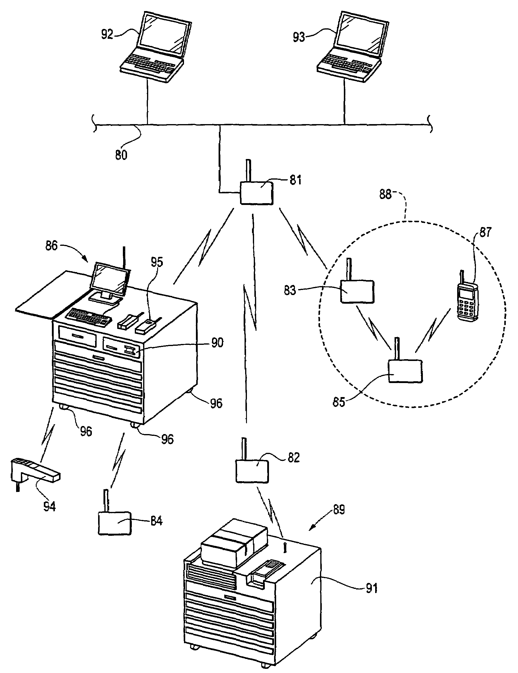
[0027]The present invention solves the foregoing problems in a longer range communication network having a mobile service station comprising a plurality of network devices. One of the plurality of network devices is an access point device which is capable of communicating on the longer range communication network. The plurality of network devices together form a shorter range communication network operating as a subnetwork in the longer range communication network. The access point device may enter a low power consumption state when it is not communicating on either the longer range communication network or the shorter range communication network.

Problems solved by technology

Hard-wiring poses several problems.
This place a strain on the input / output capabilities of many computer devices.
In addition, the wired mass of cabling often creates an eyesore and safety hazard.
In addition, attempts to hide cabling behind walls often proves very costly, and such hidden wires are always more difficult to relocate.
Another problem exists when several computer terminals share a peripheral device.
This poses significant problems with different types of computers that do not share a common hard-wired interface or communication protocol.
In smaller computer terminal settings, hand-held or portable terminals, the cabling and connection problem become more severe.
Physical connections created by hard-wiring often proves to be relatively expensive because cables break and must be replaced.
An operator who is using, holding or carrying several devices and feels all tied up is not just inconvenienced, he may be severely limited in his mobility and flexibility as he moves about the work area.
This loss of mobility and flexibility directly undercuts the entire reason for having small and portable computers and peripheral devices, and greatly increases the likelihood of operator injury.
Attempts to alleviate or eliminate these problems have been made but have not been greatly successful.
However, this solution proves unsatisfactory for several reasons.
For example, the incorporation of many devices into one unit greatly increases the size and weight, thus jeopardizing the portability of the unit.
Furthermore, incorporating all of the functions into one unit greatly reduces and, in most cases eliminates, the flexibility of the overall system.
An all-incorporated unit thus becomes either overly large because it must include everything, or very limiting because it does not include everything.
Other large scale wireless communications have also been developed which for RF communication between several computer terminals and peripheral devices, but all proving to be ineffective as a solution.
Although this requirement may be acceptable for stationary peripheral devices receiving virtually unlimited power (i.e., when plugged into an AC outlet), it proves detrimental to portable peripherals by unnecessarily draining battery power.
Again, often unnecessarily, battery power is wasted.
Once such terminals are installed, they cannot be easily moved without significant effort in not only moving the terminals themselves but also in the relocation of the power source (typically an AC outlet), communication network and telephone line connections.
Also in merchandising operations, a common problem is found in handling light and heavy checkout loading.
If the guess proves too low, additional stationary terminals (each requiring power source, network and telephone connection, i.e., cabling installations) must be added, often causing floor layout problems and very expensive cabling installations which require the store to be temporarily closed.
Alternately, if the guess proves too high, a merchandiser must either rip out the station and repair the facilities or suffer the costs of lost space and station upkeep.
Furthermore, increases or decreases in customer traffic over time may covert a guess for good to bad, resulting in the need to modify a store's terminal installations.
In addition, in periods of light checkout traffic (i.e., very few customers checking out in relation to the number of stationary merchandising terminals), most of the stationary merchandising terminals will not be used.
In such situations, the space taken up by the stationary terminals is not justified.
In periods of heavy checkout traffic (i.e., where numbers of customers wait in lines for access to each available stationary merchandising terminal), merchandisers fear that their customers will see the lines and forego their purchases, or, worse, will become so dissatisfied with the checkout wait that they will vow never to return.
Thus, it may be appreciated that it is often very difficult to predict the number of stationary merchandizing terminal installations that are or will be needed.
Moreover, it is even more difficult and costly to change a store's stationary merchandizing terminal installations to conform to such needs.
However, even with such changes, the aforementioned problems have not been solved.
In addition, the RF transmissions used to communicate with the centralized host need relatively high transmission power, requiring access to a virtually unlimited power source (such as is available through an AC outlet).

Method used


Image

  • Transaction control system including portable data terminal and mobile customer service station
  • Transaction control system including portable data terminal and mobile customer service station
  • Transaction control system including portable data terminal and mobile customer service station

Examples


Embodiment Construction

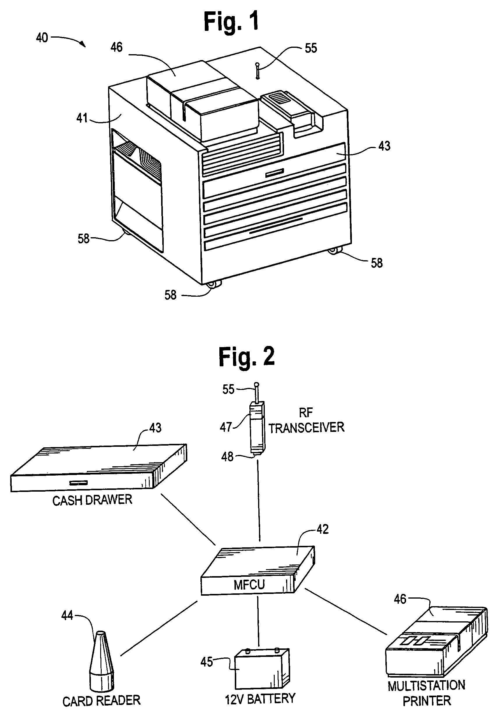
[0050]FIG. 1 is a perspective diagram illustrating a mobile customer service station built in accordance with the present invention. The devices found in the illustrative peripheral LAN are battery powered and therefore must conservatively utilize their radio transceivers. The arrangement of the communication network, communication protocols used, and data rate and power level adjustments help to optimize battery conservation without substantially degrading network performance.

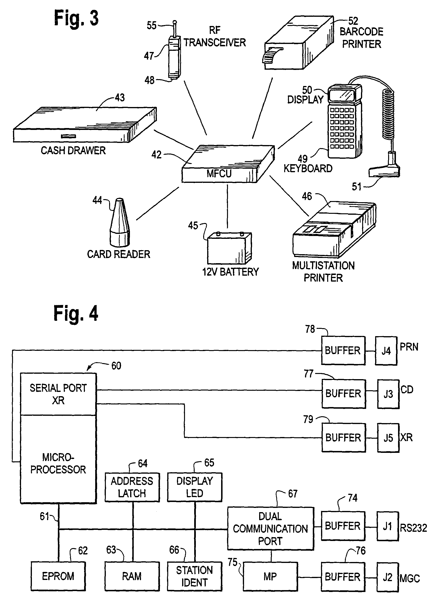
[0051]In the embodiment illustrated in FIG. 1, the station 40 comprises a radio transceiver 47 (having an antenna 55), the cash drawer 43, and the multi-station printer 46. Other components, such as the battery 45 and the multi-function control unit 42 are mounted within a housing or an enclosure 56 of the console 41. The enclosure 56 is mounted, in turn, to a wheeled base or chassis 57 which serves as a component mounting structure of the console 41 of the customer service station 40.

[0052]The enclosure 56 de...


PUM


Abstract

A mobile customer service station operating within a wireless multi-hop communication network includes a console on a wheeled chassis. The console carries and houses a number of components which are used in merchandising operations to conclude customer purchase transactions. The items supported externally on the console are a printer for printing purchase receipts, customer credit charge agreements and records of transactions, and a magnetic card reader for reading information from a magnetic stripe of a customer's credit card. In one embodiment, the operation of the printer, credit card reader and the cash drawer is controlled by a multi-function control unit located within an enclosure of the console. The control unit is electrically powered by a self-contained power source which is preferably a deep cycle rechargeable battery. The console also houses a transceiver unit which under the control of the control unit is capable of interactive communication with a premises network. In another embodiment, the mobile service station comprises an access device which participates with a variety of peripherals at the station in a lower power communication LAN, while providing higher power communication to other network devices via a premises network with routing via a wireless spanning tree configuration.

Description

CROSS REFERENCE TO RELATED APPLICATIONSClaiming Benefit Under 35 U.S.C. 120[0001]This application is a continuation of U.S. application Ser. No. 08 / 499,328, filed Jul. 7, 1995, now U.S. Pat. No. 6,654,378, which is a continuation-in-part of U.S. application Ser. No. 08 / 487,609, filed Jun. 7, 1995, now U.S. Pat. No. 5,790,536, issued Aug. 4, 1998. U.S. application Ser. No. 08 / 499,328 is also a continuation-in-part of PCT Application Serial No. PCT / US93 / 12628, filed Dec. 23, 1993.[0002]The U.S. application Ser. No. 08 / 487,609, filed Jun. 7, 1995 is a continuation-in-part of U.S. application Ser. No. a) 08 / 279,148, filed Jul. 22, 1994, now U.S. Pat. No. 5,657,317, issued Aug. 12, 1997; and b) 07 / 876,629, filed Apr. 30, 1992, now abandoned.[0003]The U.S. application Ser. No. 08 / 279,148, is a continuation-in-part of PCT Application Serial No. PCT / US94 / 05037, filed May 6, 1994; U.S. application Ser. No. 08 / 205,639, filed Mar. 4, 1994. now U.S. Pat. No. 5,555,276, and U.S. application Ser....

Claims


Application Information

Patent Timeline
Patent Type & Authority Patents(United States)
IPC IPC(8): H04B7/00G06F1/16G06K17/00G07G1/14H03C3/09H04B1/04H04L1/00H04L1/16H04L12/28H04L27/12H04L27/156H04L29/06H04L29/08H04L29/12H04M1/73H04M7/00H04W52/26H04W84/12H04W92/02
CPCG06F1/163G06Q20/20G06Q20/32G06Q20/322G07G1/0018G07G1/0081G07G1/14H04L1/0002H04L1/0003H04L1/0025H04L1/0032H04L1/1671H04L1/1685H04L27/12H04L27/156H04L29/06H04L29/12009H04L61/00H04W92/02G06K2017/0051H04B1/04H04M7/006H04W52/267H04W84/12H04L69/18H04L69/329Y02B60/50G06Q20/321H04L9/40
Inventor MAHANY, RONALD L.KOENCK, STEVEN E.BUNTE, ALAN G.MEIER, ROBERT C.MILLER, LEGAL REPRESENTATIVE, JULIE ANNWOLF, ROGER L.HANSON, GEORGE E.MILLER, PHILLIP
Owner AVAGO TECH WIRELESS IP SINGAPORE PTE
Why Eureka
Try Eureka