
Device for obtaining structure data of a moving object

a technology moving objects, applied in the field of devices for obtaining structure data of moving objects, can solve the problems of major artifacts, 3 to 10 seconds, multiple heart beats of patients, etc., and achieves improved poor local and contrast resolution, and high time resolution

Inactive Publication Date: 2008-12-30
SIEMENS HEALTHCARE GMBH
View PDF15 Cites 5 Cited by
  • Summary
  • Abstract
  • Description
  • Claims
  • Application Information

AI Technical Summary

Benefits of technology

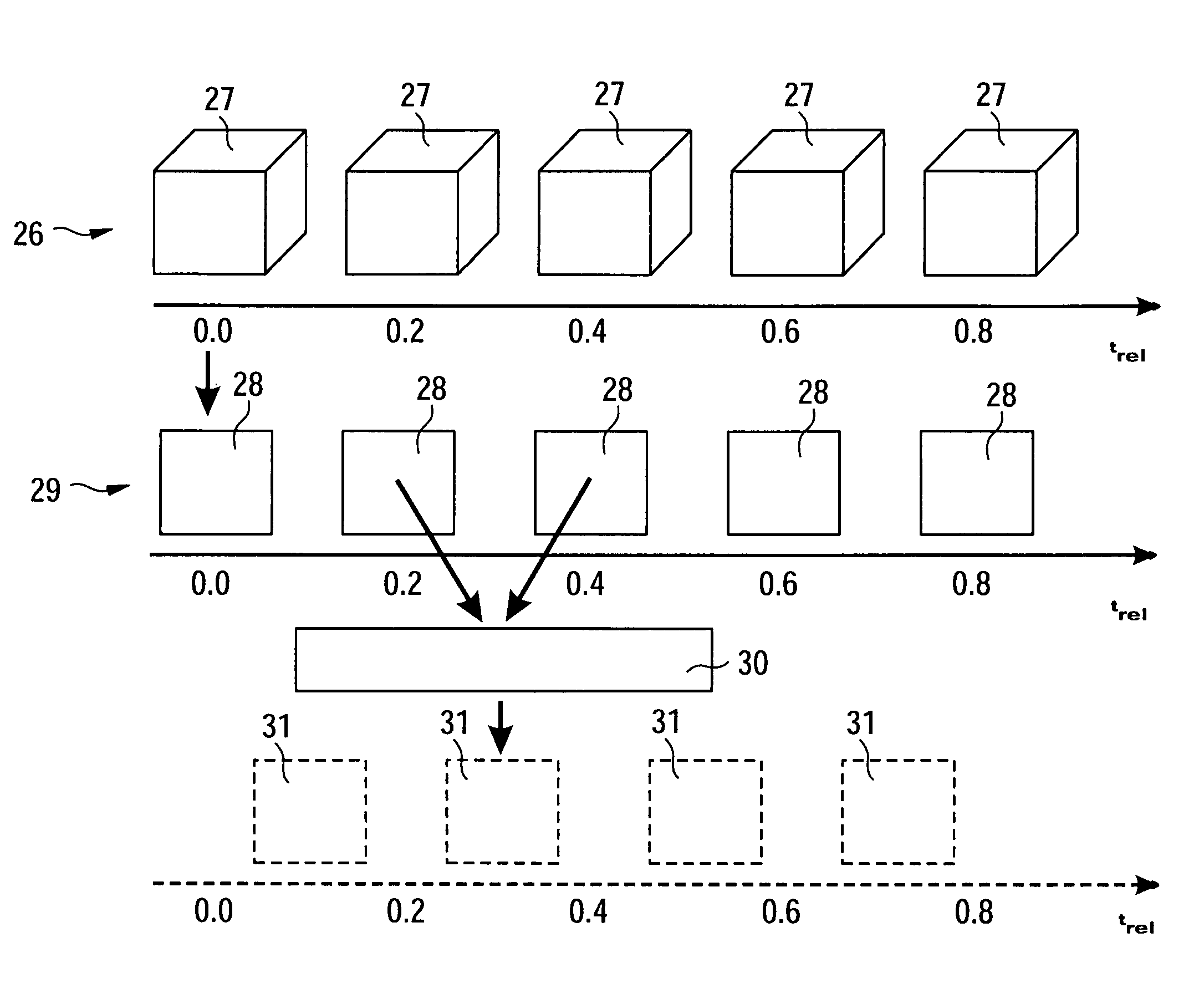
The invention is a device that can obtain structure data of a moving object with high spacial and time resolution. It uses an evaluation unit to determine an object model valid for the relevant time frame and a movement analyzer to calculate movement fields from the object model. A movement compensator then calculates movement-corrected projection images based on the movement fields, resulting in improved local and contrast resolution and a high time resolution. The device can also detect the phases of a cyclically moving object and use an electrocardiograph as a movement sensor. The evaluation unit can repeat the data reduction process until the calculated structure data sets only change slightly.

Problems solved by technology

One problem here is that the heart of a patient beats multiple times during the long rotation of the X-ray source and X-ray detector which typically takes 3 to 10 seconds.
The movement of the heart results in major artifacts during the three-dimensional reconstruction of the structure data of the heart.
This selection results in the substantial deterioration of both the spatial resolution and the contrast resolution of the three-dimensional structure data.
Conversely, it is also possible to extract more projection images for obtaining the structure data but in this case, the temporal resolution deteriorates.

Method used


Image

  • Device for obtaining structure data of a moving object
  • Device for obtaining structure data of a moving object
  • Device for obtaining structure data of a moving object

Examples


Embodiment Construction

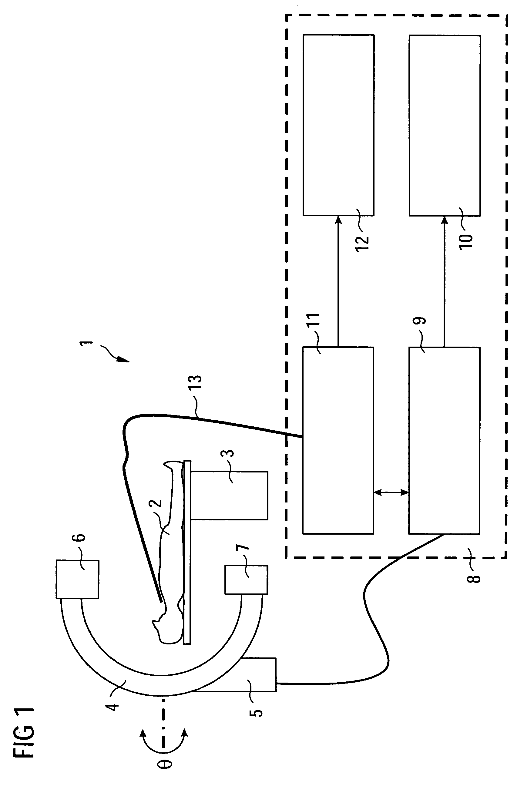
[0026]FIG. 1 shows an angiography device 1 which serves to obtain structure data from a heart of a patient 2. This structure data can be a three-dimensional model of the heart of the patient 2. The structure data can also be sections through the heart of the patient 2. Furthermore, the structure data can be obtained with or without time resolution.

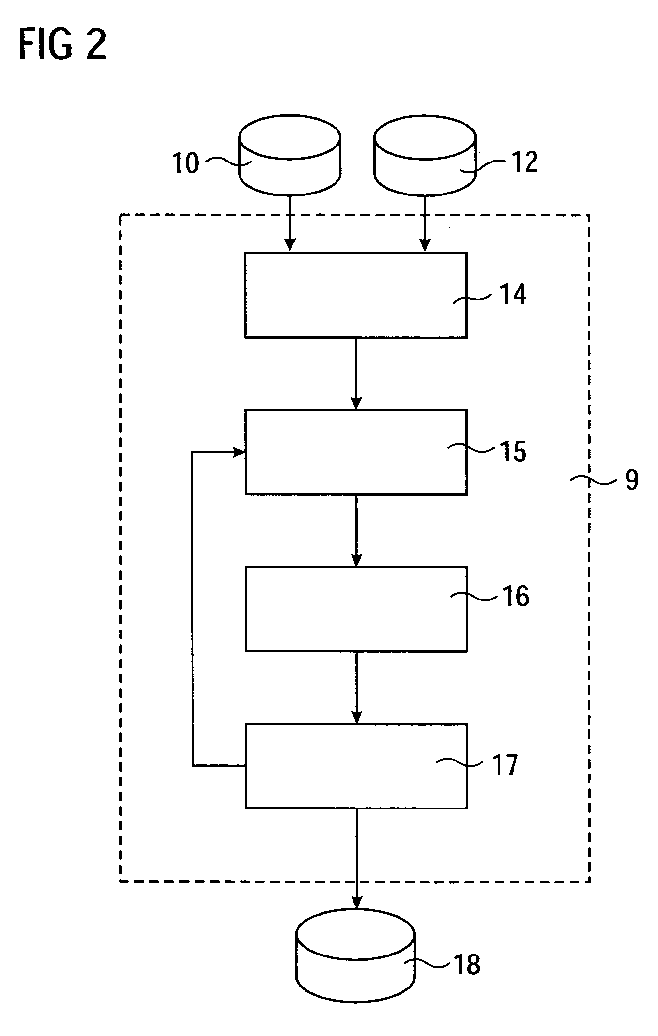
[0027]The patient 2 typically lies on a table 3, which can be rotated by a C-arm 4. The C-arm 4 is attached to a support 5 which allows the C-arm 4 to rotate about the patient 2. Furthermore, the C-arm 4 has an X-ray source 6 and an X-ray detector 7, which serves to record projection images of the heart of the patient 2. The projection images generated by the X-ray detector 7 are supplied to an evaluation unit 8, which has an image processing unit 9 with connected image memory 10 and an electrocardiograph 11 with a connected heart signal memory 12. The electrocardiograph 11 is connected to the patient 2 by means of electrodes 13.

[0028]FIG....


PUM

PropertyMeasurementUnit
rotation angiocardiographyaaaaaaaaaa
movement-aaaaaaaaaa
movementaaaaaaaaaa

Abstract

In addition to a radiation source (6) attached to a C-arm 4, and in addition to a detector (7), a rotation angiography device (1) for the angiocardiography has an evaluation unit (8), which formulates models with low resolution from the projection images supplied by the detector (7) for the moving object to be examined, and which generates movement fields for the projection images generated by the detector (7) on the basis of the model, so that movement-corrected projection images can be calculated from the projection images, which can be used to formulate a three-dimensional high-resolution model of the object to be examined.

Description

CROSS REFERENCE TO RELATED APPLICATIONS[0001]This application claims priority to the German application No. 10 2004 017 478.4, filed Apr. 8, 2004 which is incorporated by reference herein in its entirety.FIELD OF INVENTION[0002]The invention relates to a device for obtaining structure data of a moving object with:[0003]a radiation source which can be moved about an object along a measurement path;[0004]a detector arranged on the opposite side of the object and which can be moved according to the movement of the radiation source and,[0005]an evaluation unit which determines the structure data of the object from the projection images.BACKGROUND OF INVENTION[0006]A device of this type is generally known from US 2002 / 0186871 A1 and from the field of three-dimensional angiocardiography. Three-dimensional structure data of the moving heart is obtained in rotation angiocardiography, in which an X-ray source and an X-ray detector rotates about the patient at an angular range greater than 18...

Claims


Application Information

Patent Timeline
Patent Type & Authority Patents(United States)
IPC IPC(8): G01N23/00H05G1/00A61B6/00A61B5/0402A61B6/02A61B6/03G06K9/00G06T7/20
CPCA61B6/504A61B6/541G06T11/005G06T2211/404G06T2211/412
Inventor BOESE, JAN
Owner SIEMENS HEALTHCARE GMBH
Learn More