System for mounting wall panels to a wall structure

a wall structure and wall panel technology, applied in the field of wall systems, can solve the problems of increasing the work required to assemble the wall panels, providing unsightly appearance, and long and tedious job of mounting the wall panels to the wall structure, and achieves the effects of increasing the structural integrity of the wall structure, facilitating assembly, and being easy to manufacture and us

Inactive Publication Date: 2009-01-06
BILGE HENRY H
View PDF18 Cites 47 Cited by
  • Summary
  • Abstract
  • Description
  • Claims
  • Application Information

AI Technical Summary

Benefits of technology

[0007]It is another object of the present invention to provide a wall system which does not require the use of screws to secure the wall panels to the fastening extrusions.
[0009]It is yet another object of the present invention to provide a wall system that is easy to assemble with an existing wall structure.
[0010]It is a further object of the present invention to provide a wall system in which the fastening extrusions are secured flush against the existing wall structure by fastening devices, thereby increasing the structural integrity thereof.
[0011]It is a still further object of the present invention to provide a wall system that is easy and economical to manufacture and use.

Problems solved by technology

However, the securement of wall panels to the wall structure is generally a long and tedious job since it entails using fastening devices such as nails and / or screws to secure the walls panels directly to the wall structure.
In addition, the fastening devices are exposed, which can provide an unsightly appearance.
However, because of the L-shape at the bends at the edges of the wall panels, it is necessary to separately secure each bend to a fastening extrusion by screws, in addition to securing the fastening extrusions to the wall structure by screws, further increasing the work required to assemble the wall panels.
This means that the main bodies of the fastening extrusions are spaced away from the existing wall structure, thereby providing a further weak link in the structure, besides making it more difficult to assemble.

Method used


Image

  • System for mounting wall panels to a wall structure
  • System for mounting wall panels to a wall structure
  • System for mounting wall panels to a wall structure

Examples


Embodiment Construction

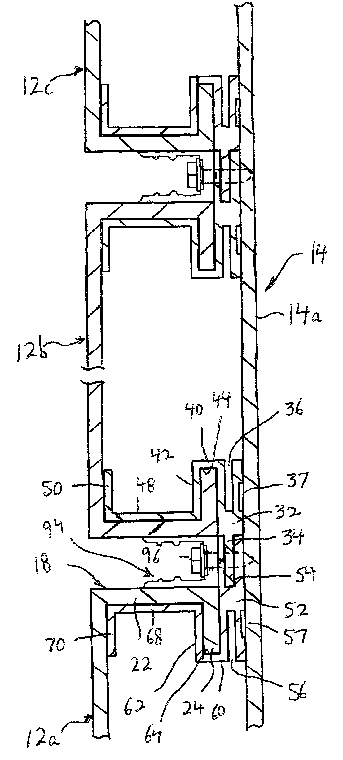
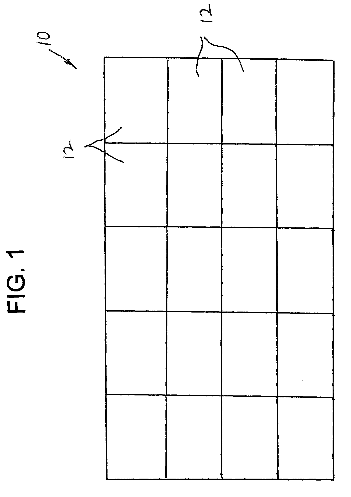
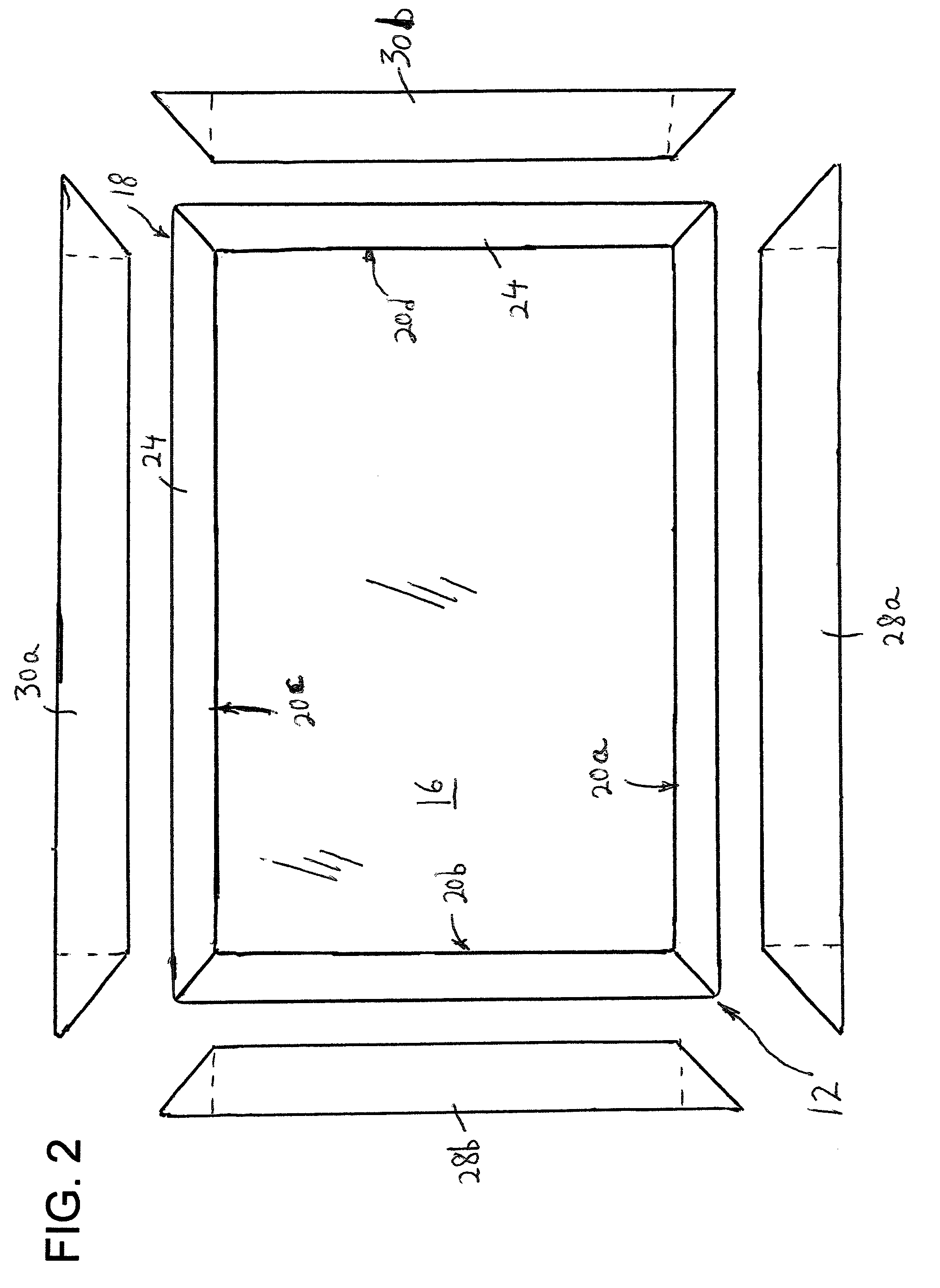
[0030]Referring to the drawings in detail, and initially to FIG. 1-4 thereof, there is shown a system 10 according to a first embodiment of the present invention for easily mounting wall panels 12 over an existing wall structure 14. Wall structure 14 preferably includes any planar wall. Each panel 12 includes a rectangular shaped, planar main panel section 16 and an L-shaped bend 18 at each edge. As a result, planar panel section 12, together with L-shaped bend 18, forms a U-shaped hook structure 20 at each edge. Specifically, each L-shaped bend 18 includes a first right angle panel section 22 at each free side edge of main panel section 16 which extends at a right angle away from main panel section 16, and a second right angle panel section 24 which extends inwardly at a right angle from the free side edge of first right angle panel section 22 such that each second right angle panel section 24 is positioned behind main panel section 16 in spaced, parallel relation thereto.

[0031]Mai...


PUM


Abstract

A system for mounting wall panels to an existing wall structure, includes a plurality of wall panels, each wall panel having a main panel section and hook walls at edges of the main panel section, with the main panel section and each hook wall having a U-shaped cross-sectional profile. There are also a plurality of fastening extrusions. Each fastening extrusion includes a securing section for securing the fastening extrusion to the existing wall structure, and a retaining wall structure at one end of the securing section, the retaining wall structure including a recess which receives one hook wall of the wall panel.

Description

BACKGROUND OF THE INVENTION[0001]The present invention relates generally to a wall system, and more particularly, to a system for easily mounting wall panels over an existing wall structure.[0002]In order to enhance the look of a wall structure, it is known to secure decorative wall panels to the wall structure. However, the securement of wall panels to the wall structure is generally a long and tedious job since it entails using fastening devices such as nails and / or screws to secure the walls panels directly to the wall structure. In addition, the fastening devices are exposed, which can provide an unsightly appearance.[0003]A system that overcomes some of these problems is sold by Bamco Inc. of 30 Baekeland Ave., Middlesex, N.J. 08846 under the designation “G500 WALL SYSTEM.” With this system, the wall panels are provided with right angle or bends at their edges. Each planar panel and the right angle bend together form an L-shape. Each bend is secured by screws to a fastening ext...

Claims


Application Information

Patent Timeline
Patent Type & Authority Patents(United States)
IPC IPC(8): E04F13/07E04B2/18
CPCE04F13/0814
Inventor BILGE, HENRY H.
Owner BILGE HENRY H
Why Eureka
Try Eureka