Portable insertable probe assembly

a probe and assembly technology, applied in the field of probe insertion, can solve the problems of inconformity with applicable standards, prohibitive cost of installing inconvenient installation of a fixed probe at each sample location, so as to achieve enhanced safety

Inactive Publication Date: 2009-01-06
MAYEAUX HLDG
View PDF25 Cites 26 Cited by
  • Summary
  • Abstract
  • Description
  • Claims
  • Application Information

AI Technical Summary

Benefits of technology

[0017]Unlike the prior art, the present invention provides an assembly for insertion and retraction of a probe or probe-like device which does not require a seal or packing gland. For a given insertion / retraction length, the required insertable probe assembly length is considerably less than that of prior art devices and since dynamic sealing of the probe which is known to leak fluids is not required with the present invention, safety is enhanced.
[0019]Said valve is opened so as to allow fluid communication between the pressurized fluid source, and the interior of the housing assembly. Fluid flow will occur until the pressure of the housing assembly and the fluid source are equal to each other. The probe can now be lowered through an opening in the first end of said housing assembly without having to overcome the force exerted by the differential pressure across a dynamic seal, as is the case with prior art.
[0020]This allows for relatively simple means of inserting / retraction of the probe into and from the pressurized fluid. A preferred means of the preferred embodiment of the present invention for insertion / retraction is the use of the rack and pinion, wherein the rack in fabricated on the probe and the pinion, anchored in the housing assembly, is rotated manually.
[0022]The second end of said conduit is attached, and fluidly sealed to, the inner wall of the second end of said housing assembly. The inner diameter of the conduit is larger than the outer diameter of the probe. The first end of the probe extends inside the conduit. A sliding seal is established between the inner wall of the conduit and the outer wall of the probe. This allows the interior space of the probe and conduit to maintain fluid isolation with the space interior to the housing assembly, and exterior to the probe and conduit.
[0024]Therefore, when the probe housing assembly is attached to a pressurized fluid pressure source through a fully opening valve, the probe can be manually inserted to a desired depth in the pressurized fluid source, thereby providing a fluid path between said pressurized source and said outlet port.

Problems solved by technology

In many cases, the cost of installing a fixed probe at each sample location is cost prohibitive.
Outfitting each sample tap location could cost several million dollars.
The result is that fluids are often sampled without the use of probes, which results in non-conformance of applicable standards, and inaccurate sample analysis.
The apparatus of these aforementioned patents are bulky and long, requiring, at a minimum, a length of at least twice the maximum insertion length to extend above the point of insertion into a vessel.
In many cases, such as in the tight quarters of a chemical plant, refinery, or offshore drilling platform, the bulk and length of these type devices preclude their use.

Method used


Image

  • Portable insertable probe assembly
  • Portable insertable probe assembly
  • Portable insertable probe assembly

Examples


first embodiment

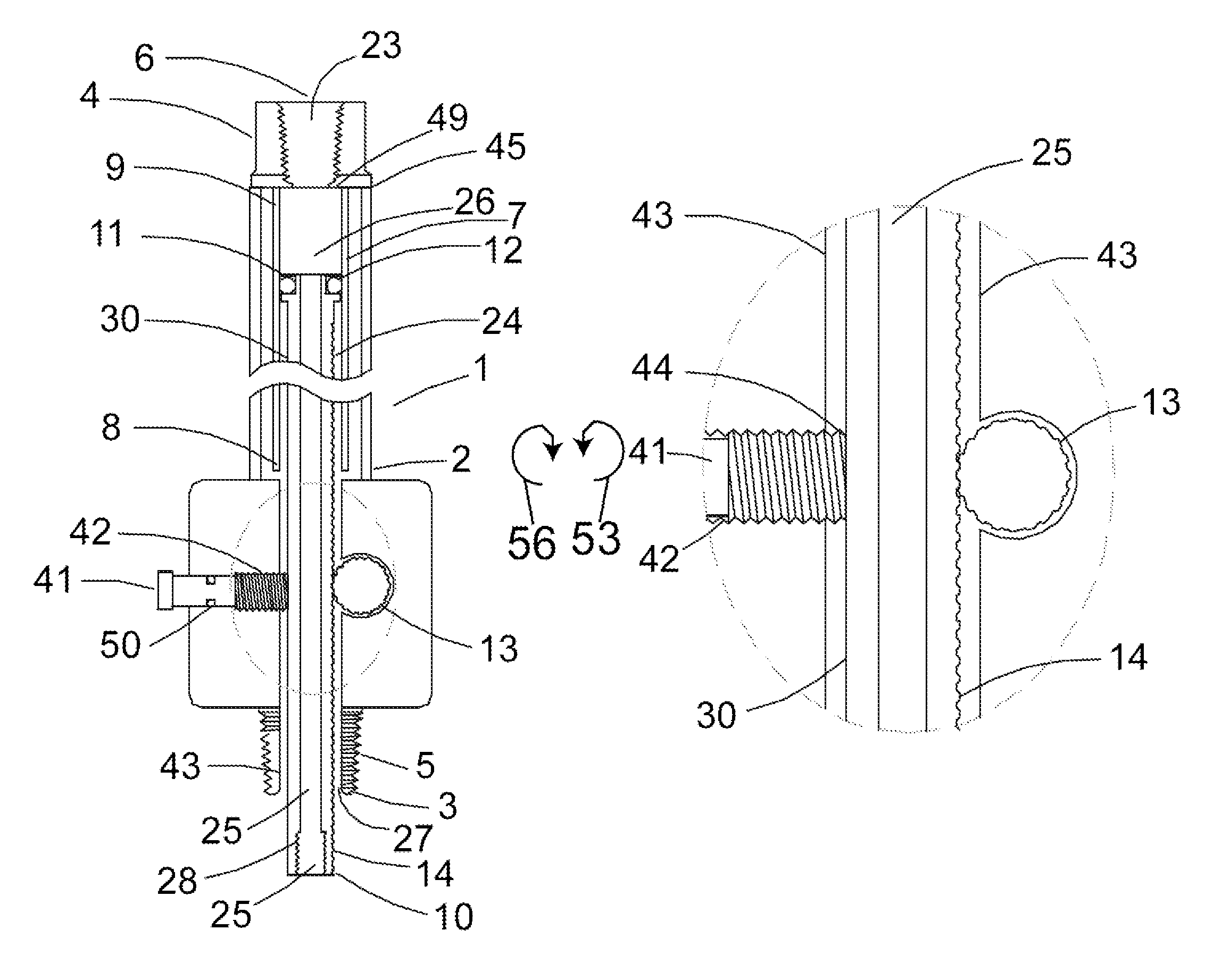
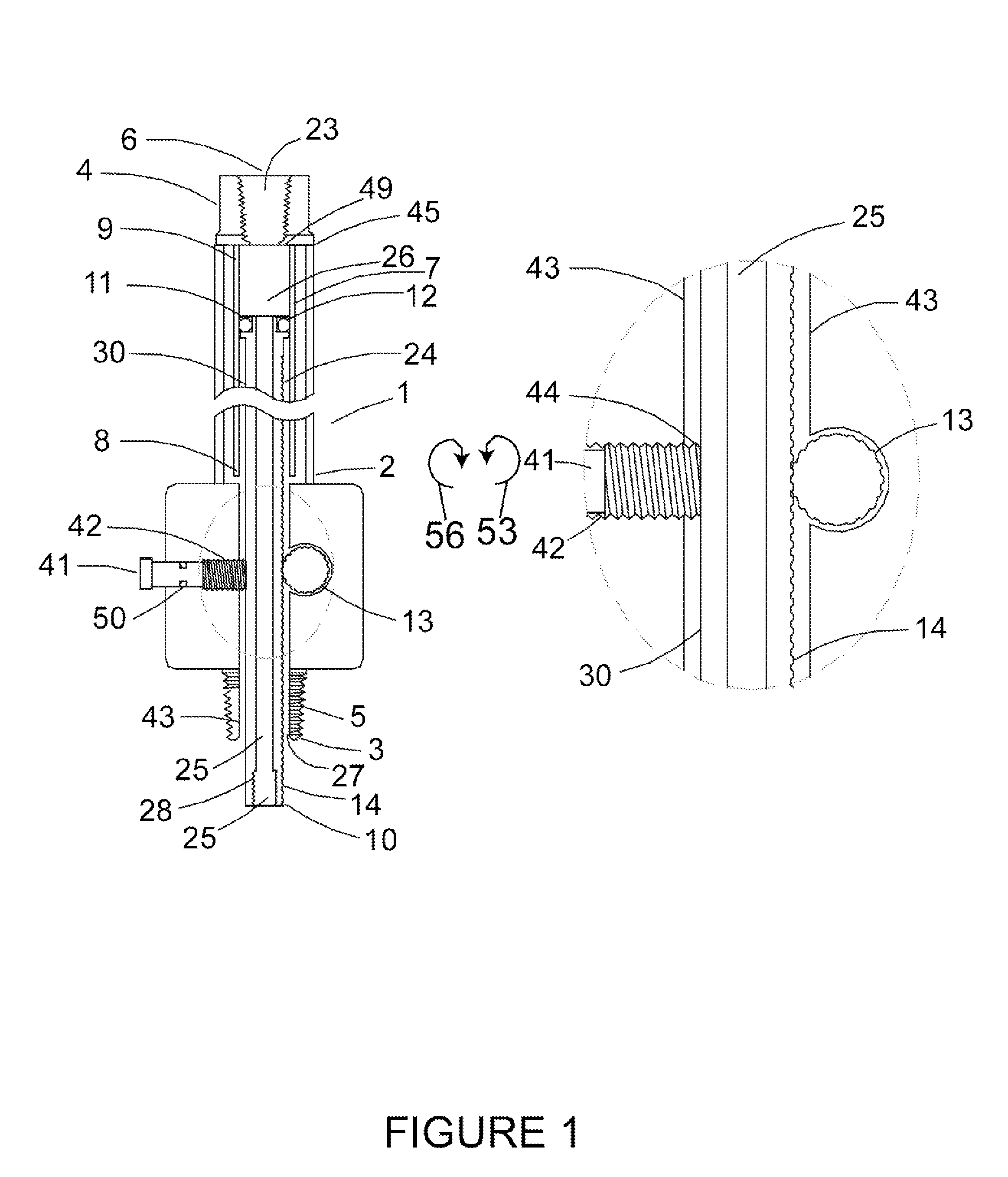
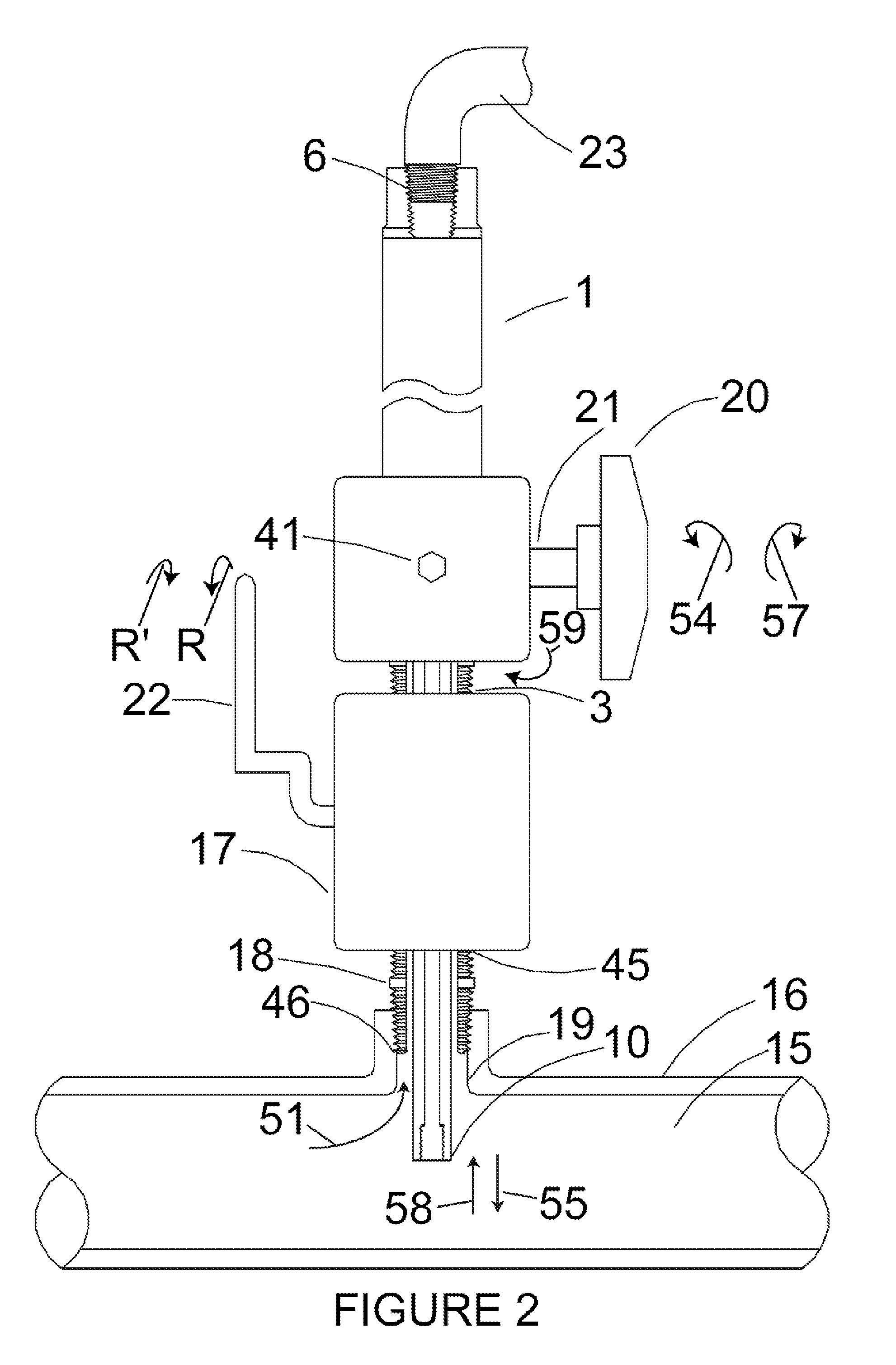
[0038]Referring to FIGS. 1 and 2, the preferred first embodiment of the invention contemplates a probe housing assembly 1 comprising a probe 30, conduit 7, and housing assembly 2. Cavity A 24, formed within housing assembly 2, extends longitudinally from the first end 3 of housing assembly 2 to the second end 4 of housing assembly 2. Cavity A 24 is formed between the inner wall 43 of housing assembly 2, and is external to conduit 7. Threaded outlet port 6 is formed in the second end 4 of housing assembly 2, and male NPT threads 5 are formed in first end 3 of housing assembly 2.

[0039]The second end 9 of conduit 7 is attached and fluidly sealed to the inner wall 49 of the second end 4 of housing assembly 2. The first end 8 of conduit 7 extends into cavity A 24. Sliding seal 12 is formed on second end 11 of probe 30, said second end 11 of probe 30 being inserted into the open end of first end 8 of conduit 7, said sliding seal 12 providing fluid seal between the outer wall of second end...

fourth embodiment

[0050]In a preferred fourth embodiment of the invention (Refer to FIG. 4) a sensor 31 is attached to threaded opening 28 to passage A25, said sensor 31 having communication cable 32 extending through passage A 25, passage B, and outlet port 6. Operation for extending sensor 31 into pressurized fluid process 15 is essentially the same as for preferred first embodiment.

fifth embodiment

[0051]In a preferred fifth embodiment shown in FIG. 5 attachment plate for corrosion coupon 33 is attached to threaded opening 28 to passage A 25 which can then be inserted into a pressurized fluid process 15 in a manner similar to that described for first preferred embodiment.

[0052]In a sixth preferred embodiment (Refer to FIG. 6) a closed end cap 34 having a finned outer surface 40 is attached to threaded opening 28 to passage A 25 which effectively seals off said threaded opening 28 to passage A.

[0053]Thus, a well is formed, comprised of closed end cap well 35, passage A 25, passage B 26, and threaded outlet port 6. A temperature sensor 36 or other similar object can now be lowered (at its first end 38) into the closed end cap well 35, which remains open to the atmosphere even when probe 30 is extended into pressurized fluid process 15. A temperature sensor cable 48 relays the signal from the probe at the second end 39 of the temperature sensor 36. Operation of this sixth preferr...


PUM

PropertyMeasurementUnit
lengthaaaaaaaaaa
pressureaaaaaaaaaa
atmospheric pressureaaaaaaaaaa

Abstract

An assembly for insertion and retraction of probe or probe-like device which does not require a seal or packing gland, instead utilizing pressure equalization between pressurized process fluids and the housing containing a probe, so as to negate the use of a dynamic seal. The preferred embodiment of the present invention contemplates an inserting / retraction mechanism for raising and lowering the probe into and from the pressurized fluid, respectively. A housing having a valve is configured to allow fluid communication between the pressurized fluid source, and the interior of the housing assembly. A conduit engages the housing assembly, and is formed to slidingly receive the outer diameter of the probe therethrough, such that a sliding seal maintains a fluid seal between the outer wall of the probe and the inner wall of the conduit, as the probe is telescoped therethrough during insertion and retraction of the probe into / from the pressurized process. Fluid flow will occur until the pressure of the housing assembly and the fluid source are equal to each other. The probe is then lowered through an opening in the first end of the housing assembly without having to overcome the force exerted by the differential pressure across a dynamic seal. An example of the insertion / retraction mechanism of the present invention utilizes a rack and pinion system.

Description

[0001]The present application claims the benefit of Provisional Application 60 / 646,332 filed Jan. 24, 2005 entitled “Portable Insertable Probe Assembly”.TECHNICAL FIELD OF THE INVENTION[0002]The present invention relates to the insertion of a probe into a pressurized process. Insertion of a probe into a pressurized process is often required for the purpose of extracting fluid samples, measuring fluid temperature, insertion of corrosion coupons and many other uses.[0003]The preferred embodiment of the present invention contemplates a system configured to insert a probe though the sidewall of a containment vessel, whereas a pressure equalization technique is utilized in lieu of a probe packing gland or seal. Safety is improved by eliminating potential seal leaks. The length and size of the assembly is smaller than current means, the complexity of operation is reduced, and the overall cost for fabrication is reduced.BACKGROUND OF THE INVENTION[0004]The heating value of natural gas has ...

Claims


Application Information

Patent Timeline
Patent Type & Authority Patents(United States)
IPC IPC(8): G01M19/00G01M99/00G01N1/00G01N1/20G01N17/04G01N27/28
CPCG01N1/2035G01N1/2247G01N17/046G01N27/283G01N35/1079G01N2001/2261
Inventor MAYEAUX, DONALD P.
Owner MAYEAUX HLDG
Why Eureka
Try Eureka