Vibration reduction apparatus for power tool and power tool incorporating such apparatus

a technology of vibration reduction and power tools, which is applied in the direction of manufacturing tools, portable power-driven tools, drilling machines, etc., can solve the problems of affecting the use of the apparatus itself, so as to achieve the effect of adjusting the tension of the biasing means with a considerable degree of sensitivity

Inactive Publication Date: 2009-01-06
BLACK & DECKER INC
View PDF54 Cites 11 Cited by
  • Summary
  • Abstract
  • Description
  • Claims
  • Application Information

AI Technical Summary

Benefits of technology

[0020]By using a torsional biasing means to urge the axle means towards the first position, the advantage is provided that the biasing means can be of particularly compact construction since it can extend around or within the axle means. This results in a significant reduction in the space required within the housing to provide effective damping. Furthermore the torsional biasing means does not add significantly to the weight of the device and is surprisingly effective, for its weight, in vibration reduction when compared to devices of the prior art.
[0037]By providing the adjusting means such that the rotation of the cam results in movement of the biasing means in a direction which is substantially parallel to axis of rotation of the cam, the advantage is provided that a large movement of the lever can result in a small movement of the portion of the biasing means which is engaged with the cam. This therefore allows for considerable sensitivity in the adjustment in the tension of the biasing means.

Problems solved by technology

Known hammer drills of this type suffer from the drawback that the hammer action generates significant vibrations, which can be harmful to users of the apparatus, and can cause damage to the apparatus itself.
This rocking motion of the handle is extremely uncomfortable and can be dangerous to the user of the power tool.
In particular, the rocking motion is then damped by flexing of the user's wrist, and such repeated flexing sustained by regular-long term use of the power tool could lead to a number of debilitating disorders.
However, because handles 102 move through an arc there remains a twisting element to the motion of handles 102 as a result of which the device described in EP0033304 cannot easily be adapted to devices of the type shown in FIG. 1.
Another problem with devices of the prior art is that the vibration damping device are large, requiring additional space within the housing of the power tool, and the additional components add weight to the tool, which is also undesirable.
A further problem associated with the prior art is that under different circumstances different spring tensions produce more effective damping of vibrations.
However, such devices typically require the housing of the tool to be removed in order to access the tension adjusting means.
As a result the tension is rarely adjusted and the full benefit of the vibration damping apparatus is not utilised.

Method used


Image

  • Vibration reduction apparatus for power tool and power tool incorporating such apparatus
  • Vibration reduction apparatus for power tool and power tool incorporating such apparatus
  • Vibration reduction apparatus for power tool and power tool incorporating such apparatus

Examples


Embodiment Construction

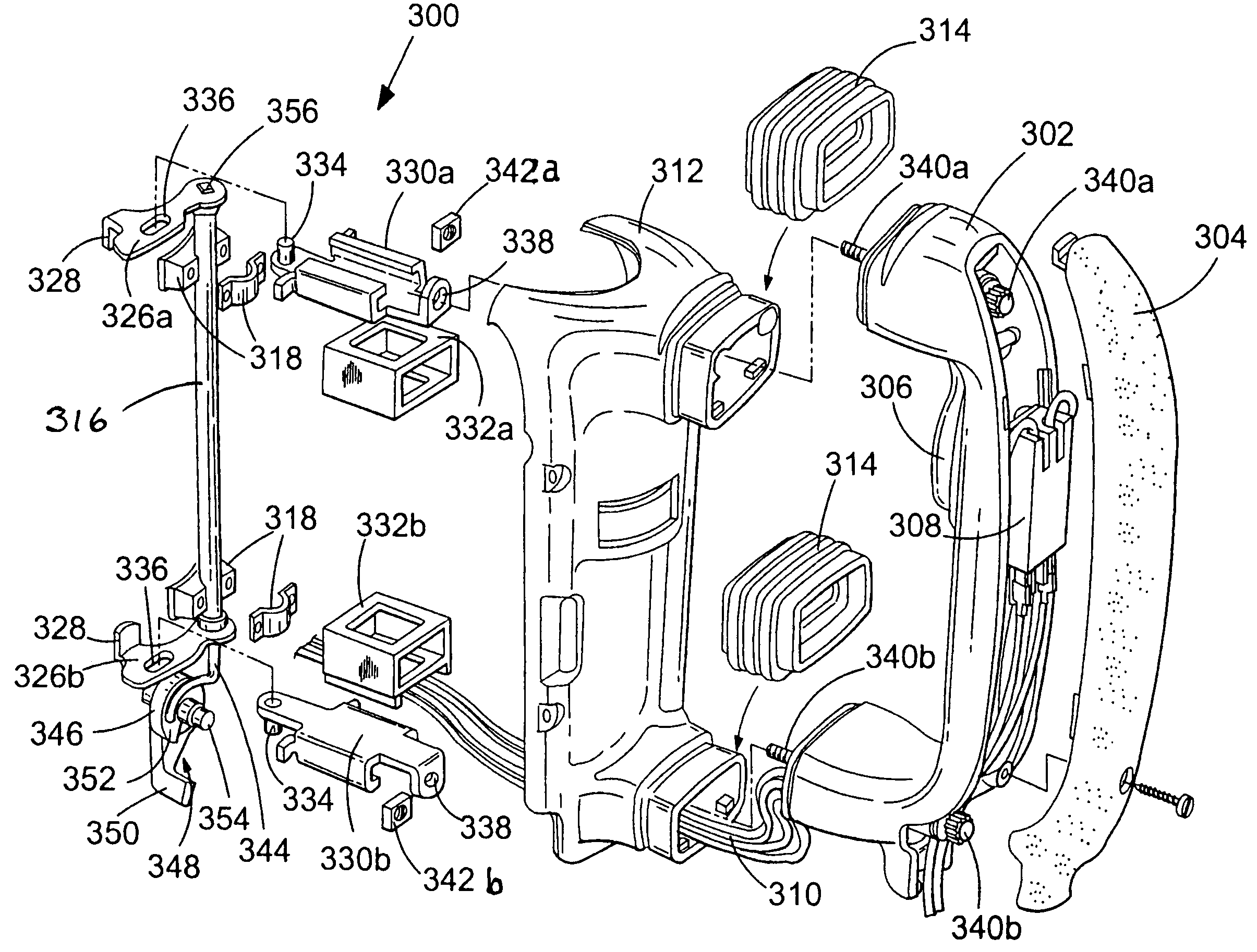
[0046]Referring to FIG. 3, a handle assembly 300 for use as part of a power hammer (not shown) has a handle 302 which has a rubberised gripping portion 304. Handle 302 also has a trigger 306 which activates switch 308 and provides power to the hammer mechanism via cables 310.

[0047]Handle 302 is mounted to the housing 312 of the power tool, only a portion of which is shown in FIG. 3, and handle 302 is capable of limited movement relative to housing 312. Rubberised sleeves 314 cover the joint between handle 302 and housing 312.

[0048]The handle assembly also has a hollow axle 316 which is attached to the housing 312 by brackets 318 and is able to rotate relative to the housing 312 between a first position and a second position. Axle 316 is biased towards said first position by biasing means in the form of a torsional spring 344. Torsional spring 344 extends within hollow axle 316 and is fixed at one end relative to housing 312 by engaging portion 346 which engages adjusting means 348 b...


PUM

PropertyMeasurementUnit
rotational movementaaaaaaaaaa
movementaaaaaaaaaa
axis of rotationaaaaaaaaaa

Abstract

A power hammer has a handle mounted to a housing and capable of limited movement relative thereto. A hollow axle is attached to the housing and is rotatable between a first and second position and is biased towards the first position by a torsional spring which extends within the axle. Rotation of the axle causes rotation of arms connected thereto. Connectors are slidably mounted within guides and are respectively connected at one end to each of the arms and at the other end to the handle. Vibrations in the housing cause movement of one end of the handle, which causes movement of the associated connector and arm. Movement of the one arm causes rotation of the axle, which therefore causes movement of the other arm and connector, and the other end of the handle. Thus, the movement of one end of the handle is coupled to the other end.

Description

FIELD OF THE INVENTION[0001]The present invention relates to vibration reduction apparatus for power tools and to power tools incorporating such apparatus. The invention relates particularly, but not exclusively, to vibration reduction apparatus for power hammers, and to hammers incorporating such apparatus.BACKGROUND OF THE INVENTION[0002]Electrically driven hammers are known in which a driving member in the form of a flying mass is reciprocally driven in a piston, and impact of the flying mass against the end of the piston imparts a hammer action to a bit of the hammer. Such an arrangement is disclosed in European patent application EP1252976 and is shown in FIG. 1.[0003]Referring in detail to FIG. 1, the prior art demolition hammer comprises an electric motor 2, a gear arrangement and a piston drive arrangement which are housed within a metal gear housing 5 surrounded by a plastic housing 4. A rear handle housing incorporating a rear handle 6 and a trigger switch arrangement 8 is...

Claims


Application Information

Patent Timeline
Patent Type & Authority Patents(United States)
IPC IPC(8): B25D17/24B25D17/00B25D17/04B25F5/02
CPCB25D17/043B25D2222/57B25D2250/371
Inventor STIRM, MICHAELBECHT, REIMUNDHAHN, NORBERT
Owner BLACK & DECKER INC
Why Eureka
Try Eureka