Pelvic floor training device

a training device and pelvic floor technology, applied in the field of pelvic floor training devices, can solve the problems of only being used by one individual, worn directly against the skin,

Active Publication Date: 2009-01-06
MSYS
View PDF6 Cites 14 Cited by
  • Summary
  • Abstract
  • Description
  • Claims
  • Application Information

AI Technical Summary

Benefits of technology

[0006]The object of the invention is to provide a training device for the pelvic floor muscles, which device renders it possible to measure the pressure or force in a defined and convenient manner on the pelvic floor muscles.
[0009]The present invention provides a training device having a pressure force sensor unit such that the force emitted by the pelvic floor muscles can always be coupled vertically. This is possible because the pressure force sensor unit can be compressed on all sides and the pressure force sensor unit is located during the operation between the ischial bones of the pelvic floor. In the absence of any muscle activity only the gravitational force which can be compensated electronically has an effect. The training device according to the invention comprises few components and it can be manufactured in a convenient manner.
[0010]The training device according to the said invention can be used without it having to be worn on the body. This is more hygienic than known training devices and it measures more accurately owing to the pressure force sensor system and the seated position of the user. During tensing of the pelvic floor a muscle pressure force occurs which can be measured precisely.
[0014]The training device according to the invention can comprise a receiving seat element in which the pressure force sensor unit can be positioned. The training device is as a consequence easy to use and can be integrated on the seating surface of a chair or as the a seat of a fitness device or the like. A device for adjusting the height of the pressure force sensor unit in relation to the seat part can be provided. By virtue of an arrangement of the pressure force sensor unit which is comfortable for the user it is possible to achieve an improved contact with the force transducer which improves the signal quality.

Problems solved by technology

Moreover, a great disadvantage of training devices of this type is that they must be worn directly against the skin in order to be effective.
This means that such a device can only be used by one individual or must be thoroughly cleaned before or after use.

Method used


Image

  • Pelvic floor training device
  • Pelvic floor training device
  • Pelvic floor training device

Examples


Embodiment Construction

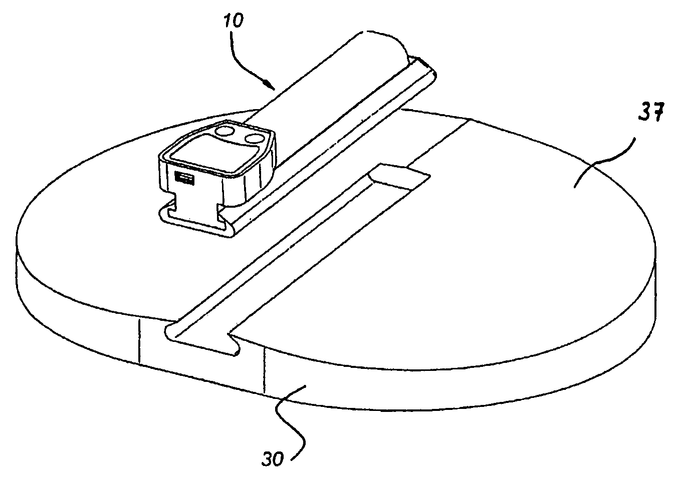
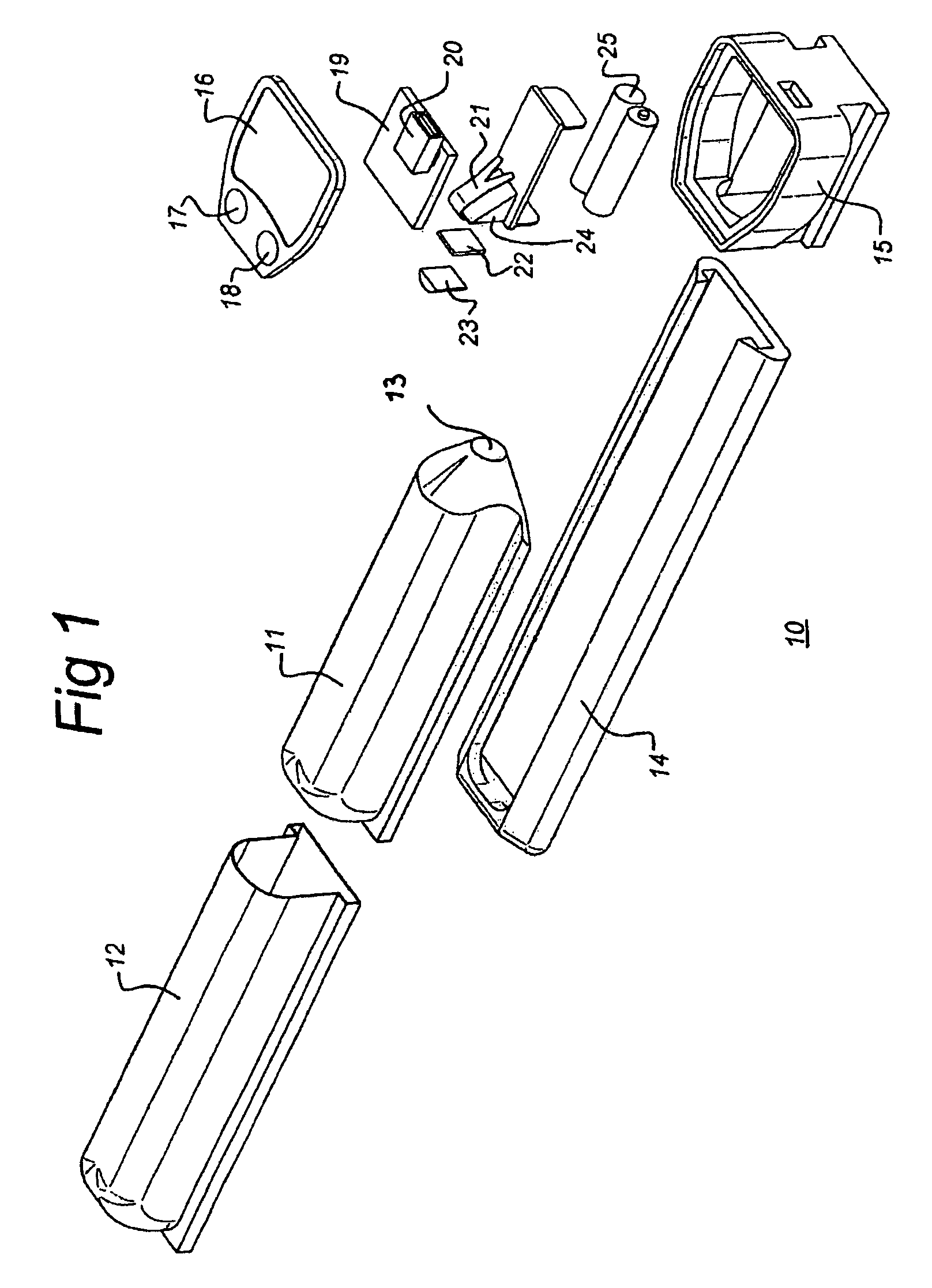
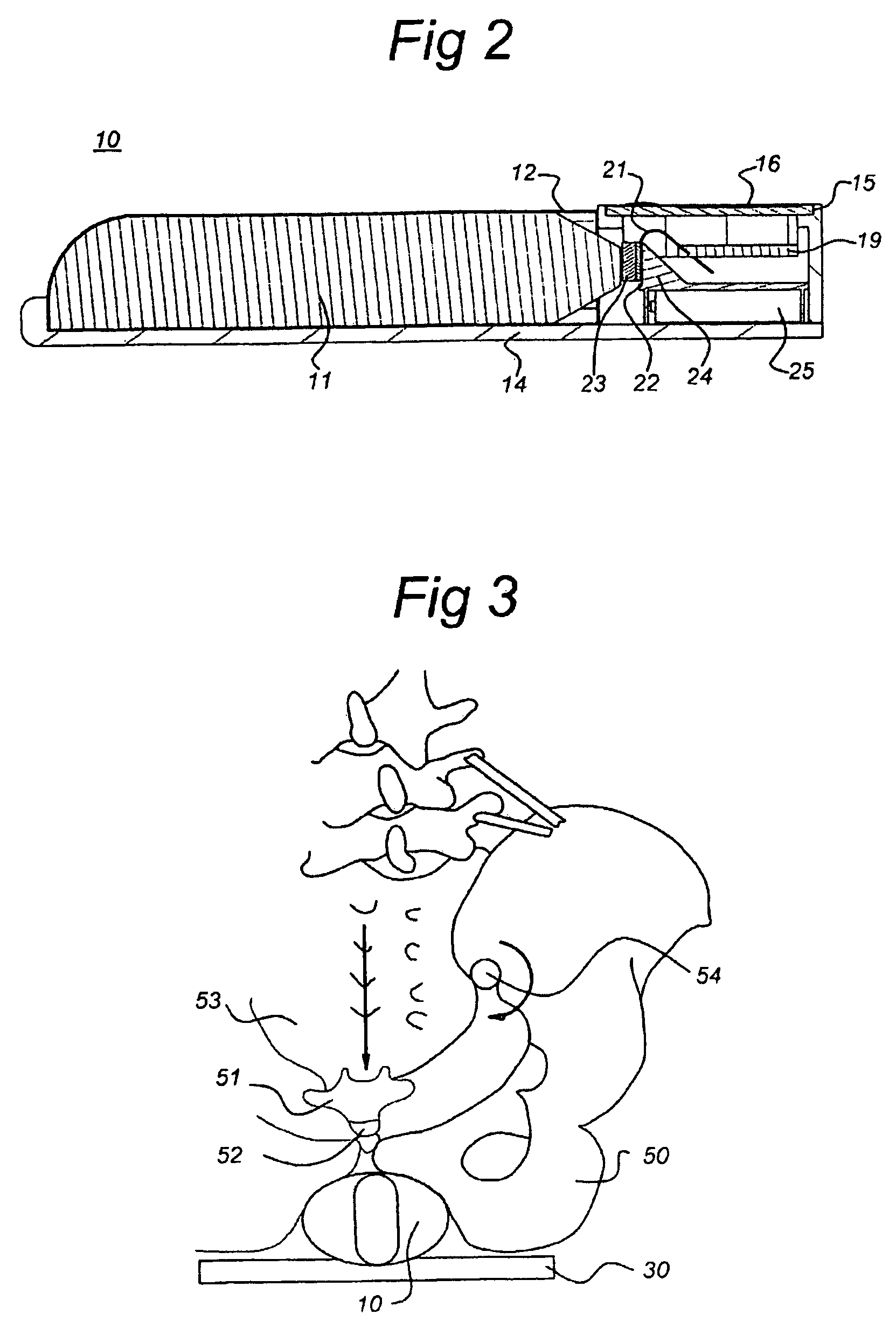
[0021]FIG. 1 shows an exploded view and FIG. 2 shows a cross-sectional view of a first embodiment of the training device 10 for the pelvic floor muscles according to the invention.

[0022]The training device 10 comprises an easily deformable part (fill media: fluids, gels or gases in a spherical body or the like) as a pressure force sensor unit 11, which is held in a shell-like body 12 which can expand in the radial direction but not in the axial direction. The shell-like body 12 ensures that the pressure force sensor unit 11 can deform, i.e. can be compressed, by means of the force of pressure only in the radial direction. The shell-like body can only expand in the axial direction on the sensor-side end face 13.

[0023]The combination of the pressure force sensor unit 11 and the shell-like body 12 can be held in a base plate 14. The pressure force sensor unit 11 is for example manufactured from an elastic spherical body which is filled with fluid, gel or gas.

[0024]In addition, a housin...


PUM


Abstract

A training device for training the pelvic floor muscles of a human, which can be externally placed on the human body and can be connected to feedback units that produce feedback signals, such as vibrations. The training device is, at least on one side, aligned with the pelvic floor, can be compressed and can be axially deformed on its sensor side. A pressure force sensor unit of the training device can be positioned during the operation in such a manner that the ischial tuberosities of the pelvic floor can be situated on both sides on the pressure sensor unit, and a gravitational force component passing through the pelvic floor acts upon the pelvic floor training device, making a precise measurement of the exertion on the pelvic floor possible.

Description

[0001]This application is a filing under 35 USC 371 of PCT / EP2005 / 001730 filed Feb. 18, 2005.FIELD OF THE INVENTION[0002]The present invention relates to a device which is used for training the muscles in the pelvic floor of a human being. The device contains pressure or force transducers which are placed externally on the human body. The extremely soft muscles are coupled to a suitable pressure force sensor unit with feedback facilities whilst the person is seated and thus by virtue of gravitational force.PRIOR ART[0003]A training device for the same problems is known for example from U.S. Pat. No. 5,531,226 A. The known training device comprises a tubular body which elastically expands after compression. The document does not define precisely where this tubular body can be compressed. Moreover, a great disadvantage of training devices of this type is that they must be worn directly against the skin in order to be effective. This means that such a device can only be used by one ind...

Claims


Application Information

Patent Timeline
Patent Type & Authority Patents(United States)
IPC IPC(8): A63B26/00A61B5/03A61B5/22A63B23/20A63B24/00
CPCA63B23/20A63B2071/0625A63B2220/51
Inventor SCHUURMANS STEKHOVEN, MARCOBRINKHAUS, BERNHARDNOTEN, KARELKWANT, HENDRIKSPIERENBURGH, SPLINTER JUSTUS
Owner MSYS
Why Eureka
Try Eureka