Amplifier comprising an electronic tube provided with collectors biased by at least two DC bias sources

an amplifier and electronic tube technology, applied in the field of amplifiers, can solve the problem of the potential difference between the collector and the voltage source of low value, and achieve the effect of minimizing the size and cost of the voltage source and improving reliability

Inactive Publication Date: 2009-01-06
THALES SA
View PDF5 Cites 2 Cited by
  • Summary
  • Abstract
  • Description
  • Claims
  • Application Information

AI Technical Summary

Benefits of technology

[0022]This configuration thus allows sources of lower voltage value than in the prior art to be used and the size and cost of the voltage sources to be minimized.
[0023]Moreover, it is no longer required to synchronize the power-up and the shut-down operations of the voltage sources since it is not possible for the potential difference between the collectors to exceed that of the voltage source of low value. This improves the reliability of this type of equipment and preserves the tube.

Problems solved by technology

Moreover, it is no longer required to synchronize the power-up and the shut-down operations of the voltage sources since it is not possible for the potential difference between the collectors to exceed that of the voltage source of low value.

Method used


Image

  • Amplifier comprising an electronic tube provided with collectors biased by at least two DC bias sources
  • Amplifier comprising an electronic tube provided with collectors biased by at least two DC bias sources
  • Amplifier comprising an electronic tube provided with collectors biased by at least two DC bias sources

Examples


Embodiment Construction

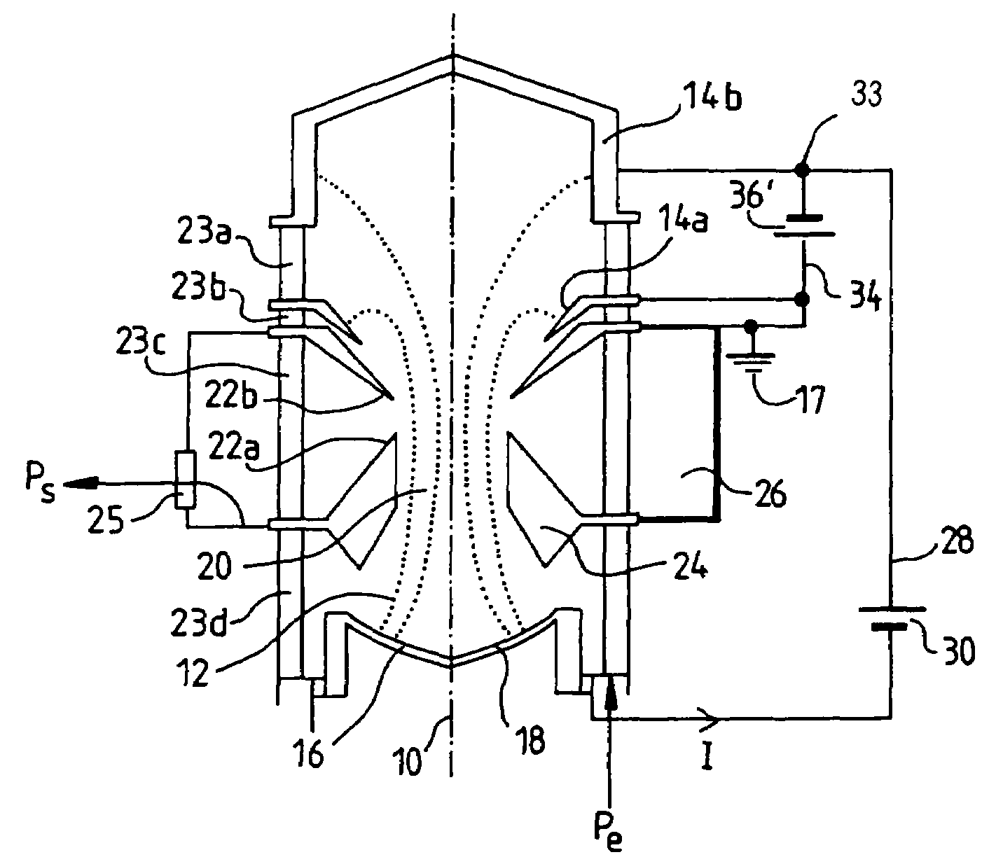
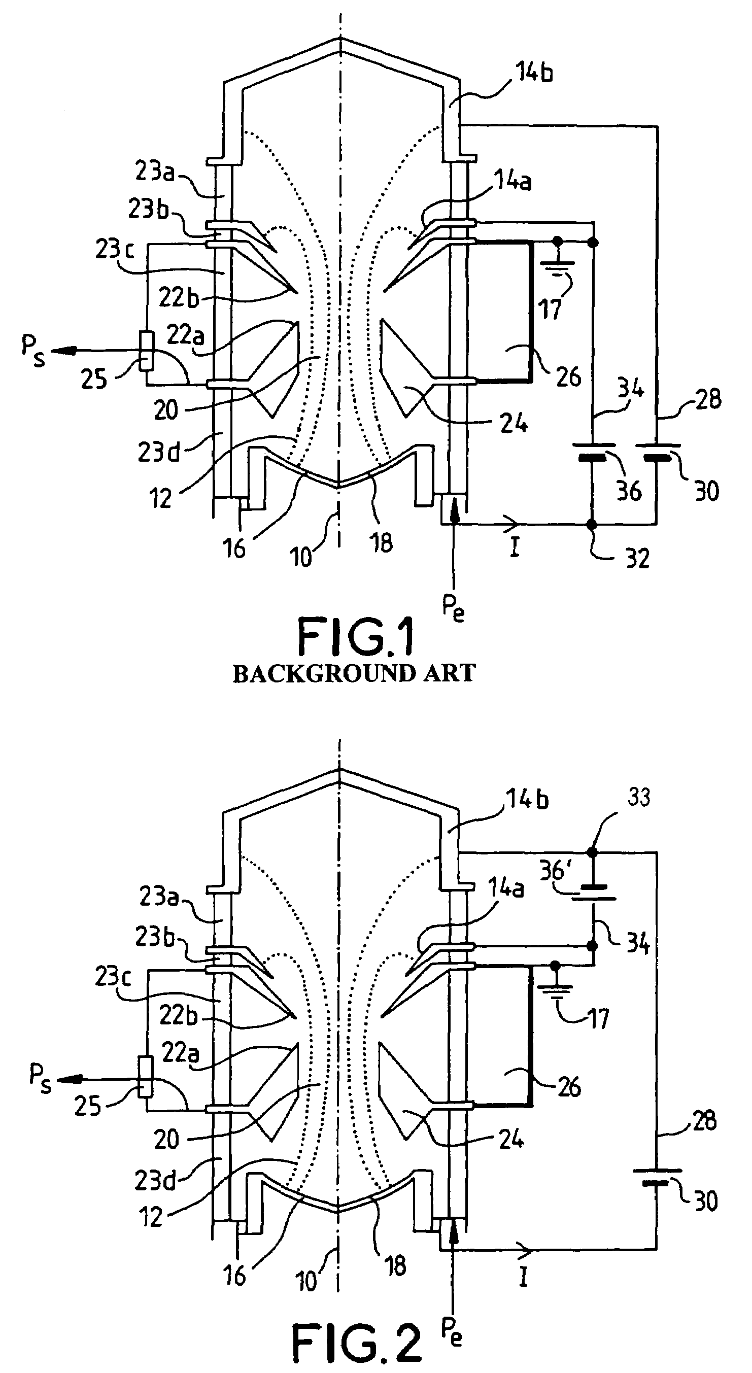
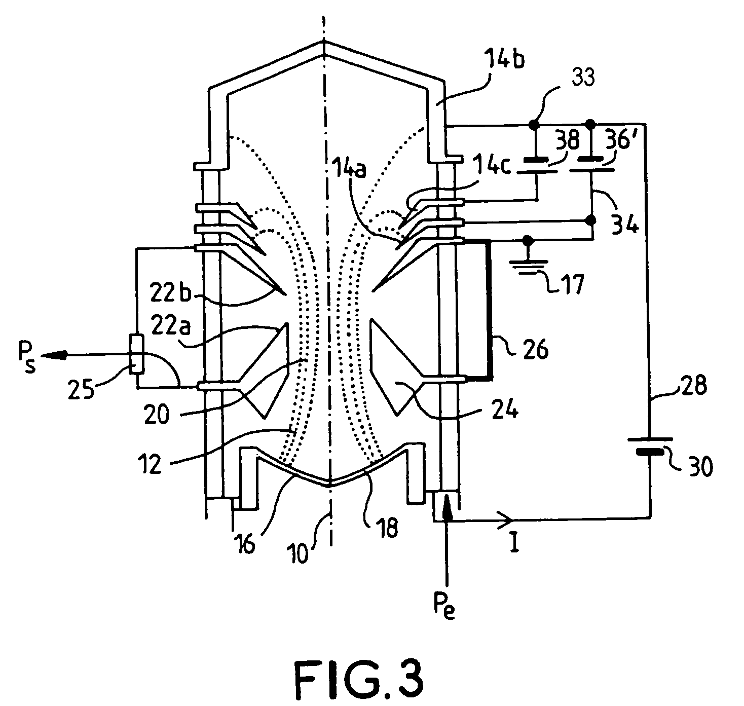
[0033]FIG. 2 shows an exemplary embodiment of an amplifier implementing the invention; it comprises an inductive output electron tube with at least two collectors. It comprises two collectors 14a and 14b in the example in the figure. The invention may also be applied to traveling wave tubes or klystrons and, more generally, to any electron tube with an axial electron beam.

[0034]The collector 14b is connected to the positive pole 28 of a DC voltage source 30, for example of 26 kV. The negative pole of the DC voltage source 30 is connected to the cathode 16.

[0035]The collector 14a is connected to the positive pole 34 of a DC voltage source 36′, for example of 8 kV. The negative pole of this voltage source 36′ is connected to the collector 14b; it is in series with the voltage source 30. The common point 33 of these two voltage sources 36′ and 30 is at the collector 14b, in other words at the collector that is the farthest from the cathode. The output cavity 26 is also connected to the...


PUM


Abstract

An amplifier including an electronic tube with an axial electron beam, provided with a cathode and at least two collectors, and at least two sources of DC voltage. Each collector is connected to a DC voltage source having a potential difference such that, the further the collector is from the cathode, the lower the potential difference between this collector and the cathode. The DC voltage sources are connected together at a common point situated at the collector whose potential difference with the cathode is the lower but not zero.

Description

BACKGROUND OF THE INVENTION[0001]1. Field of the Invention[0002]The invention relates to an amplifier that comprises an electronic tube with an axial electron beam and voltage sources; the electron tube comprises at least two collectors, each collector being connected to a voltage source.[0003]The field of the invention is that of the power amplification of UHF signals, in particular the amplification of analog and digital television signals from terrestrial transmitters, by means of vacuum tubes comprising an axial electron beam.[0004]A vacuum tube uses the principle of the interaction between an electron beam and an electromagnetic wave in order to transfer to the wave a part of the power contained in the electron beam, so as to obtain at the output of the tube a wave of higher power than that of the wave injected at the input of the tube.[0005]Several categories of vacuum tube exist. In traveling wave tubes, or TWTs, and klystrons, the electron beam is modulated in velocity. In i...

Claims


Application Information

Patent Timeline
Patent Type & Authority Patents(United States)
IPC IPC(8): H01J23/027H01J23/34
CPCH01J23/027H01J23/0275H01J23/34H01J25/04H04B7/155
Inventor BEL, CLAUDE
Owner THALES SA
Why Eureka
Try Eureka