Method for object identification and sensing in a bounded interaction space

a technology of object identification and interaction space, applied in the direction of speed measurement using gyroscopic effects, instruments, surveying and navigation, etc., can solve the problems of inability to provide extensible architecture that can support existing media tables, difficult to precisely locate objects on the surface of tables, and no early attempts to point to a general purpos

Active Publication Date: 2009-01-06
MASSACHUSETTS INST OF TECH
View PDF3 Cites 56 Cited by
  • Summary
  • Abstract
  • Description
  • Claims
  • Application Information

AI Technical Summary

Benefits of technology

[0034]The important considerations for object sensing on an interactive media surface that provides multiple points of control are: the ability to track multiple objects at once, the ability to avoid interference between the tracked objects and between these objects and their surroundings, and the ability to scale the sensing surface to different sizes and aspect ratios.
[0041]Many of the technical approaches to interactive tables have required a large amount of external infrastructure, such as sensors placed around the room or overhead projection systems to provide a visual display on the table's surface. While these systems work reasonably well for prototyping or demonstration purposes within a research laboratory, they are not viable options for a media table that is designed for use within a home setting. For the latter case, both the sensing and display technologies need to be encased within the interactive table itself. Ideally, the table should be a single integrated unit that is not encumbered by too many wires or external connections (aside from power) and can be easily moved around a typical living room.
[0052]In the preferred embodiment, an application program executing on a personal computer coupled to the tabletop display derives the displayed visual image from the location data produced by the controller. The controller preferably executes application program interface (API) routines that permits event notifications, requests and responses to be exchanged between the controller and the application program, thus allowing the media table system to be utilized as a general purpose peripheral device by a wide variety of application programs.

Problems solved by technology

While the need for tabletop display surfaces seems to have been recognized by a number of researchers who have explored various interactive applications on tabletops, none of the early attempts point to a general purpose, economically viable tabletop display and interaction platform.
In particular, existing media tables do not provide an extensible architecture that can support a diverse range of applications that would be required for everyday use by many people.
While the technologies like GPS capable of tracking objects on a global scale are increasingly accurate and reliable, precisely locating objects on the surface of a table remains a difficult technical problem.
It should be noted that many optical or acoustic approaches that are done through the air can pose problems of occlusion if one or more objects are blocking the view of a receiver or transmitter.
In these cases, it becomes difficult to support multiple continuously interactive objects.
Another problem that often arises is the scalability of the interactive surface in terms of size or shape.
Approaches that use antenna grids rather than a small set of fixed receivers or transmitters generally require tiling in order to scale in size which can be costly and generally results in an extra level of complexity in the design of the electronics.
Interactive tables face the problem of dealing with large numbers of physical objects across many different applications and platforms.
While unique identifiers and an extensible namespace are common within the digital realm, getting computers to uniquely identify objects in the physical world is a difficult problem.
Past approaches to interactive tables have not been able to provide adequate systems for object identification and management.
Optical-based systems have generally not been able to provide an easily extensible set of interactive objects, and customizations are difficult to manage or scale.
While these systems work reasonably well for prototyping or demonstration purposes within a research laboratory, they are not viable options for a media table that is designed for use within a home setting.
The acoustic signal is typically transmitted through the air, which can result in errors if there are objects in the way between a transmitter and receiver.

Method used


Image

  • Method for object identification and sensing in a bounded interaction space
  • Method for object identification and sensing in a bounded interaction space
  • Method for object identification and sensing in a bounded interaction space

Examples


Embodiment Construction

[0069]Before describing the details of the TViews design and implementation, it is useful to first provide a quick summary of the combination of technical features that have been used to fulfill these requirements.

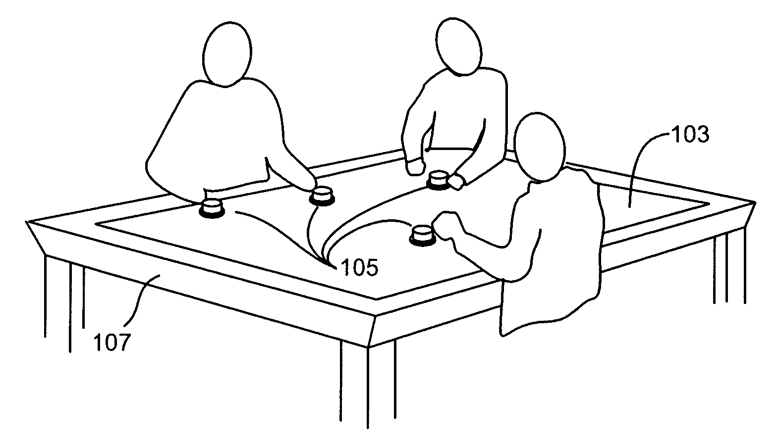
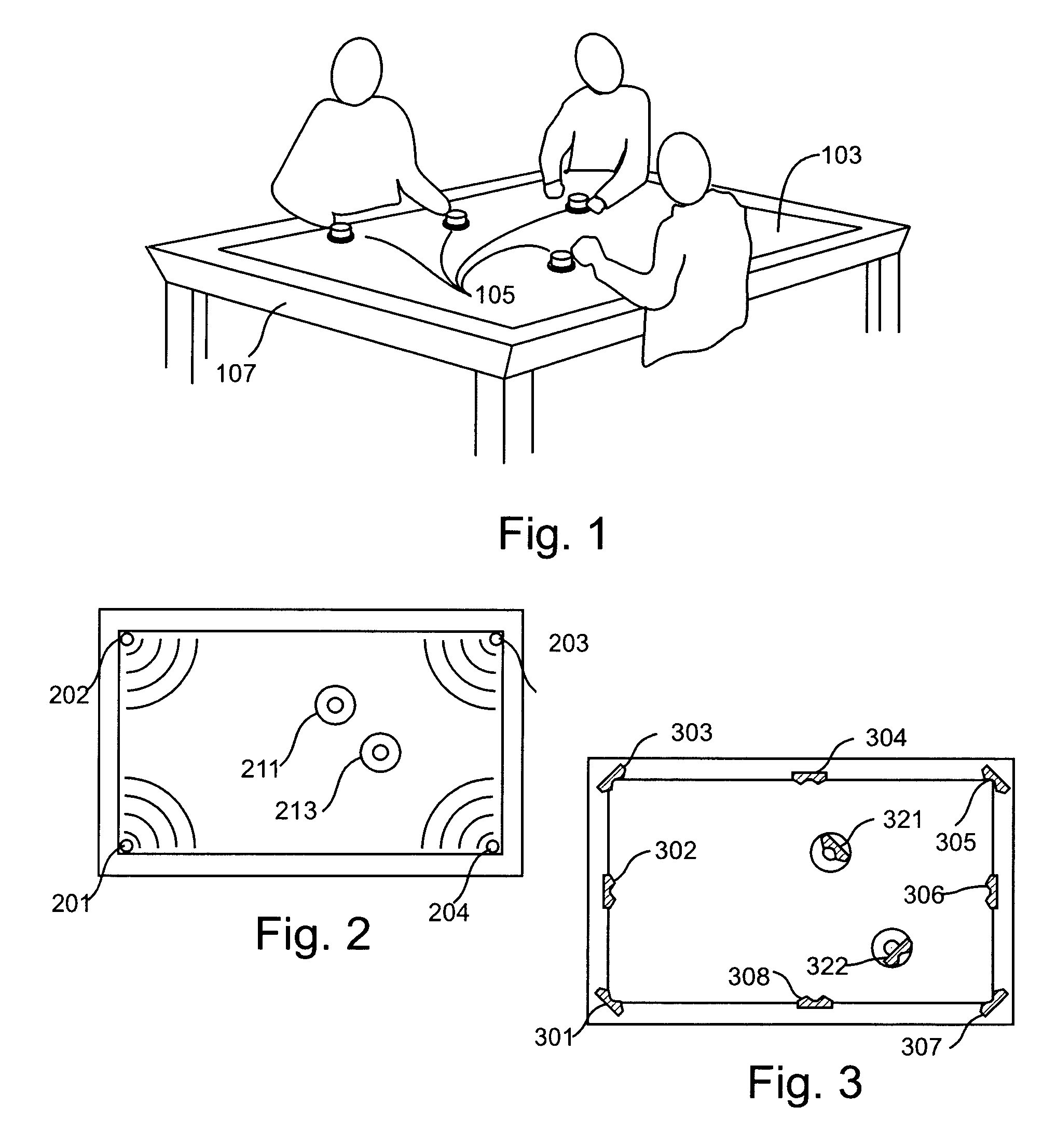
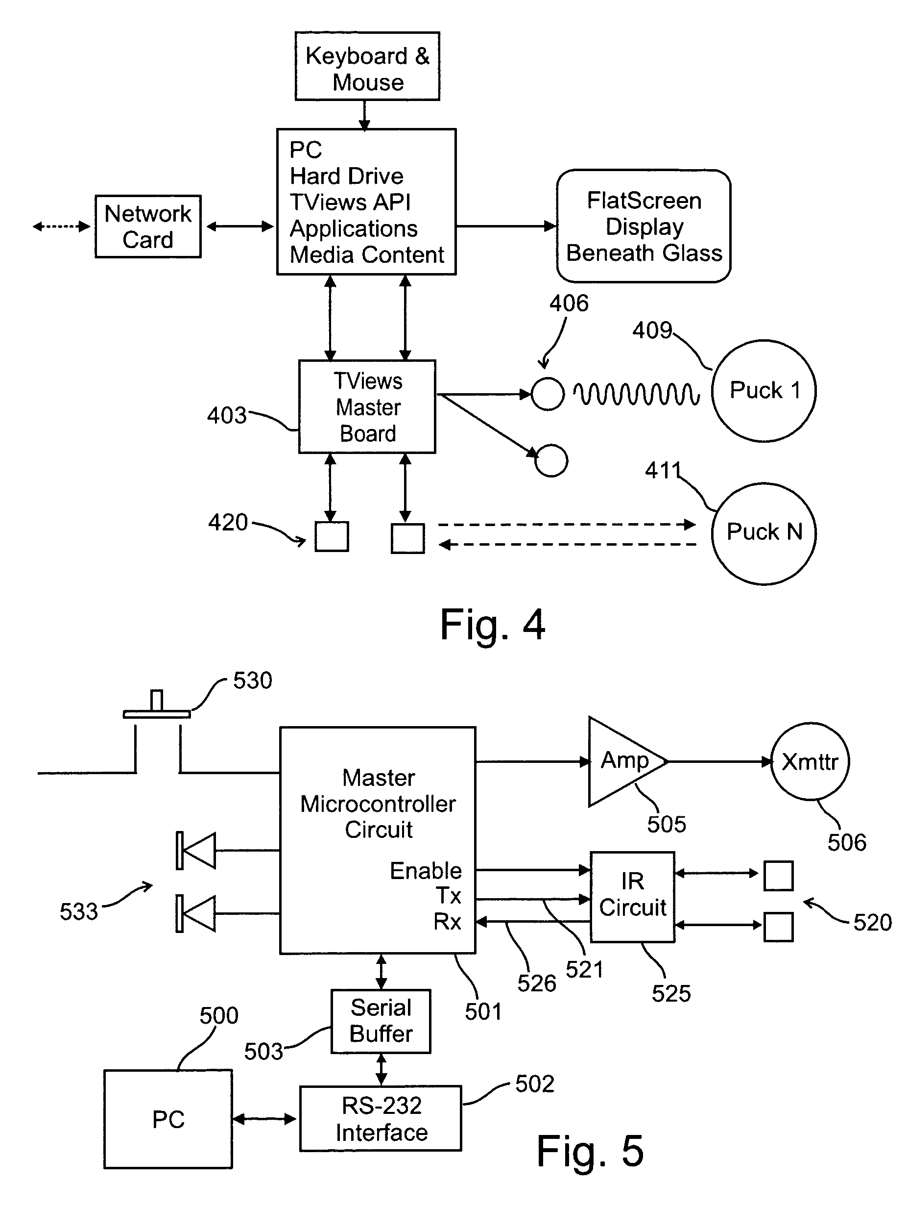
[0070](a) In order to allow scalability of the interaction surface in size, it is important that the object positioning technology operates independently of the size of the interactive surface. This can be accomplished using time-of-flight position detection, in which an object's position is triangulated based on the time it takes for signals to travel from a small number of fixed transmitters (i.e. at least two, and preferably three or more) to a receiver embedded in the object. The TViews table is based on acoustic time-of-flight. Since acoustic positioning does not require antenna grids or other materials covering the interactive surface, it is possible to embed a digital display in the table surface that is not obscured.

[0071](b) In order to provide an extensible objec...


PUM


Abstract

An interactive media table that includes a tabletop that supports of plurality of movable objects each of which is identified by a unique identification code and each of which can be moved from place to place on said tabletop surface by one or more media table users. A display unit produces a visual image on the surface of the tabletop surface and a position tracking system determines the current positions of each of said movable objects by transmitting timed acoustic signals to each movable object, sensing the timing of arrival of these signals using an acoustic pickup on each object, and estimating the location of the object by triangulation. An infrared communications network exchanges timing information, commands and data between the objects and a controller which provides an API to a personal computer which executes an application program that controls the display.

Description

CROSS REFERENCE TO RELATED APPLICATIONS[0001]This application is a non-provisional of, and claims the benefit of the filing date of, U.S. Provisional Patent Application Ser. No. 60 / 641,531 filed on Jan. 5, 2005, the disclosure of which is incorporated herein by reference.REFERENCE TO COMPUTER PROGRAM LISTING APPENDIX[0002]A computer program listing appendix is stored on each of two duplicate compact disks which accompany this specification. Each disk contains computer program listings which illustrate implementations of the invention. The listings are recorded as ASCII text in IBM PC / MS DOS compatible files which have the names, sizes (in bytes) and creation dates listed below:[0003]Firmware Listing:[0004]File NameBytesCreatedMaster16F877A.txt 9,988 bytes6 / 24 / 2004crc.txt 8,615 bytes12 / 8 / 2004ir.txt 5,286 bytes8 / 18 / 2004main.txt 8,988 bytes8 / 18 / 2004master.txt 4,279 bytes8 / 5 / 2004piezo.txt  729 bytes8 / 16 / 2004serial.txt 2,103 bytes8 / 16 / 2004Puckacoustic.txt 1,542 bytes8 / 13 / 2004crc.txt 8,61...

Claims


Application Information

Patent Timeline
Patent Type & Authority Patents(United States)
IPC IPC(8): G06F19/00
CPCG06F3/011G06F3/0433
Inventor MAZALEK, ALEXANDRADAVENPORT, GLORIANNA
Owner MASSACHUSETTS INST OF TECH
Why Eureka
Try Eureka