Projectile with means for marking its strike point

a projectile and strike point technology, applied in the field of training projectiles, can solve the problems of unsatisfactory both solutions and inability to clearly distinguish dye powders

Active Publication Date: 2009-01-13
NICO PYROTECHNIK HANNS JUERGEN DIEDRICHS GMBH & CO KG
View PDF5 Cites 39 Cited by
  • Summary
  • Abstract
  • Description
  • Claims
  • Application Information

AI Technical Summary

Benefits of technology

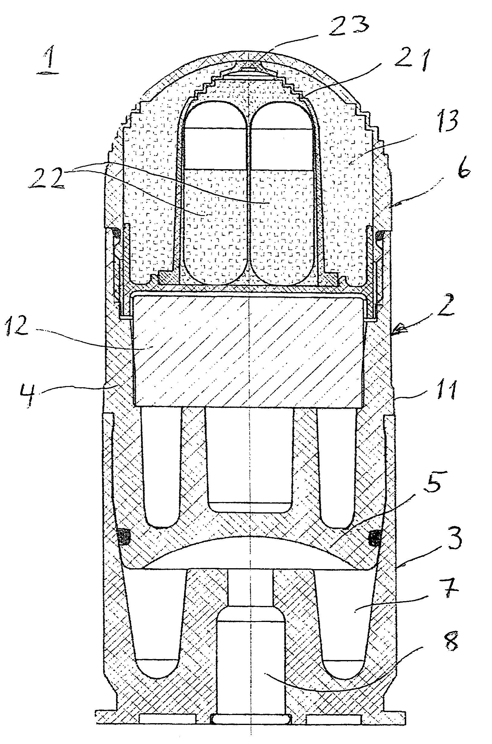
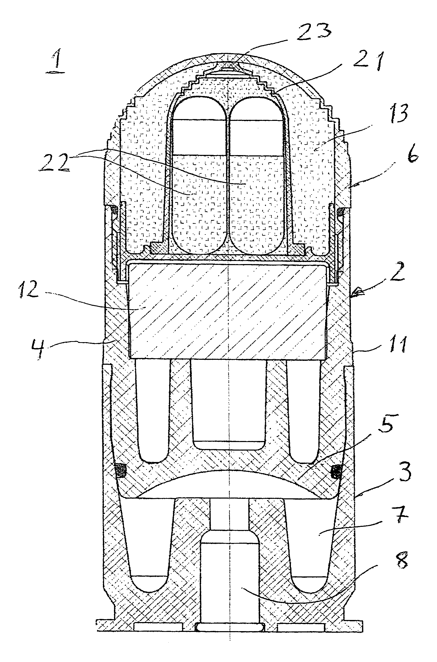
[0009]This object, as well as further objects which will become apparent from the discussion that follows, are achieved, according to the invention, by providing a training projectile which includes a hollow arched cavity or cap at its head that defines a hollow cavity within the head of the training projectile, and that bursts when the projectile strikes a target. Into this cavity are placed a first chemically-inactive marking material and a second chemically-active marking material. When the arched cavity bursts, both marking materials are released, whereby the first marking material provides a color effect and the second marking material provides a light effect.
[0010]With such a configuration of a training projectile, the strike point is made clearly visible both by day and by night. The additional light effect reinforces the color effect of the chemically-inactive marking material even under severe weather conditions.
[0014]Such a solution has the advantage that there is no high-energy material within the projectile, particularly no explosive material that might be triggered by means of heat from a catastrophic fire, for example, which greatly simplifies storage. Such ammunition is designated as “green ammunition.”
[0016]This version with pyrotechnic or explosive material has the advantage that the first chemically-inactive marking material, for example the dye powder, is distributed over a larger spatial area and is thus made more visible by means of the pressure waves of the pyrotechnic material upon impact with the target.

Problems solved by technology

Also, dye powders cannot be clearly distinguished under severe weather conditions.
Both solutions are unsatisfactory since, depending on the time of day and weather conditions, several types of projectiles must be made available.

Method used


Image

  • Projectile with means for marking its strike point
  • Projectile with means for marking its strike point

Examples


Embodiment Construction

[0019]FIG. 1 shows training ammunition 1 in cross-section view that includes a training projectile 2 mounted in a cartridge shell 3. The projectile 2 includes a projectile body 4 with a projectile bottom 5 facing toward the cartridge shell 3, and a front arched cavity 6. A propellant chamber 7 in which a propellant charge 8 is mounted is positioned within the cartridge shell 3. The propellant charge ignites upon ignition of an igniter cap, for example. The propulsive gases of the propellant charge flow into the propellant chamber 7 and act upon the projectile bottom 5. When a specific gas pressure within the propellant chamber 7 is exceeded, the connection (not shown) between the cartridge shell 3 and projectile 2 is broken, so that the projectile 2 is driven out of the cartridge shell 3.

[0020]The training projectile shown is usually fired from a weapon with a rifled barrel. A twist or guide band 11 is provided on the projectile body 4 to create the spin.

[0021]Such training ammuniti...


PUM


Abstract

A training projectile includes at its head a hollow arched cavity or cap that defines a hollow cavity within the head of the training projectile, and that bursts when the projectile strikes a target. Into this cavity are placed a first chemically-inactive marking material and a second chemically-active marking material, whereby both marking materials are released upon bursting of the arched cavity. The first marking material creates, for example, a color effect by means of a colored powder; the second marking material produces a light effect by means of, for example, materials that interact to produce chemo-luminescence.

Description

BACKGROUND OF THE INVENTION[0001]The invention relates to a training projectile whose strike point on a target or target area is optically marked.[0002]It is important in projectiles which themselves possess no live explosive charge to make the strike point visible so that optimum training results, and subsequently optimum live-fire training results, are achieved.[0003]Projectiles of the type discussed here are, for example, medium-caliber projectiles of 40 mm that are used individually or are mounted in a feed belt, and are fired in series from a rapid-fire weapon. Likewise, a dropped bomb, grenade launcher, trench mortar or similar may be simulated.[0004]Projectiles are known that include a hollow arched cavity or cap at their head that bursts upon striking a target, and into which a marking material, for example a reddish dye powder, has been inserted that is released upon bursting of the arched cavity when the projectile strikes the target. The dye material is hereby scattered f...

Claims


Application Information

Patent Timeline
Patent Type & Authority Patents(United States)
IPC IPC(8): F42B8/16
CPCF42B8/12F42B12/40F42B12/42
Inventor HAESELICH, DETLEF
Owner NICO PYROTECHNIK HANNS JUERGEN DIEDRICHS GMBH & CO KG
Why Eureka
Try Eureka